


5-48
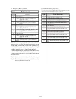
7. REC C/AFM Current Adjustment
Note:
PLAYER model:
CCD- TR317/TR517/TRV17/TRV37/TRV47/TRV57/TRV57P/
TRV67
7-1. Preparations only for the PLAYER model
1)
Select page: 0, address: 01, and set data: 01.
2)
Only for the PLAYER model, select page: D, address: 14, after
memorizing the data, set the bit value of bit1 to “1”. (Refer to
“4-3, 3. Bit value discrimination” of “5-4. Service Mode”).
3)
Select page: D, address: 15, and memorize the data.
4)
Only for the PLAYER model, select page: D, address: 15, and
set the bit value of bit7 to “0”.
5)
Insert a Hi8 ME tape, and set to VTR recording mode. (Use
the wireless remote commander of 8mm VCR, or connect Pin
od
of IC803 of VC-234 board and GND with 4.7k
Ω
resistor
for a second.)
4.7k
Ω
resistor: 1-249-425-11
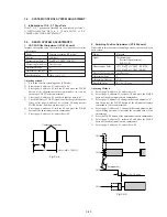
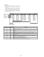
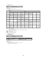
7-2. REC C Current Check (VC-234 board)
Check the recording current levels of the REC Chroma signal. If it
is too low, chroma signal noise in played back picture will be
increased. If too high, Y signal noises will increase and white
modulation noises will be produced.
Mode
VTR recording (SP mode)
Signal
No signal
Measurement Point
Pin
0
of CN982 (REC RF)
Measuring Instrument
Oscilloscope
(20 MHz BW LIMIT: OFF)
Specified Value
A=50.8 ± 3.0mV
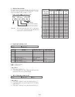
Adjusting method:
1)
Insert a Hi8 ME tape, and set to recording mode.
2)
Select page: 0, address: 01, and set data: 01.
3)
Select page: 2, address: 01, set data: 41, and press the PAUSE
button of the adjustment remote commander.
4)
Select page: 6, address: 61, and set data: 30.
5)
Select page: E, address: FB, set data: 05, and press the PAUSE
button.
6)
Select page: F, address: 71, after note down the data, set data:
00, and press the PAUSE button.
7)
Check that the REC chroma signal level (A) satisfies the
specified value, and note down the signal level.
8)
Select page: F, address: 71, set the data noted down at step 6),
and press the PAUSE button.
9)
Select page: E, address: FB, set data: 04, and press the PAUSE
button.
10) Select page: 6, address: 61, and set data: 10.
11) Select page: 2, address: 01, set data: 00, and press the PAUSE
button of the adjustment remote commander.
12) Select page: 0, address: 01, and set data: 00.
13) Perform “REC AFM Current Adjustment” and “Processing after
completed adjustment only for the PLAYER model”.
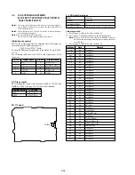
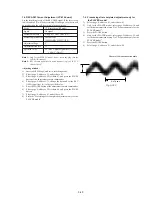
A
1.35
µ
sec
Center of the luminance line width
Fig. 5-3-12
Summary of Contents for CCD-TRV67 - Video Camera Recorder 8mm
Page 12: ...1 2 ...
Page 13: ...1 3 ...
Page 14: ...1 4 ...
Page 15: ...1 5 ...
Page 16: ...1 6 ...
Page 17: ...1 7 ...
Page 18: ...1 8 ...
Page 19: ...1 9 ...
Page 20: ...1 10 ...
Page 21: ...1 11 ...
Page 22: ...1 12 ...
Page 23: ...1 13 ...
Page 24: ...1 14 ...
Page 25: ...1 15 ...
Page 26: ...1 16 ...
Page 27: ...1 17 ...
Page 28: ...1 18 ...
Page 29: ...1 19 ...
Page 30: ...1 20E ...


