


5-50
3-5.
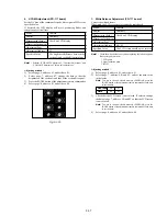
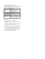
IR TRANSMITTER ADJUSTMENTS
(CCD-TRV87/TRV87P)
Adjust using a IR receiver jig (J-6082-383-A).
Note :
If the distance between the IR receiver jig and the camcorder is
below 1m, cover the LASER LINK emitter with a ND filter. (For
example, when the distance is 30cm to 50cm, cover the LASER
LINK emitter with a ND filter 1.0.)
Switch setting:
LASER LINK ........................................ ON (Red LED is lit)
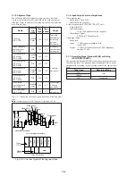
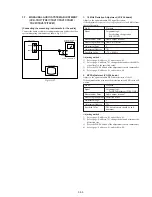
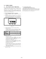
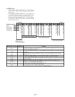
1. IR Video Carrier Frequency Adjustment
(VC-234 board)
Mode
Camera standby
Subject
Arbitrary
Measurement Point
Pin
5
of CN003 of IR receiver jig (RF)
(Or Pin
qh
of IC751 of VC-234 board)
Measuring Instrument
Frequency counter
Adjustment Page
F
Adjustment Address
80
Specified Value
f = 11.85 ± 0.05 MHz
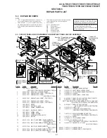
Connection of Equipment
Connect the measuring device as shown in the following figure,
and adjust.
Fig. 5-3-14.
Adjusting method:
1)
Select page: 0, address: 01, and set data: 01.
2)
Select page: 2, address: 01, set data: 37, and press the PAUSE
button of the adjustment remote commander.
3)
Select page: F, address: 80, change the data, and set the video
carrier frequency (f) to the specified value.
4)
Press the PAUSE button of the adjustment remote commander.
5)
Select page: 2, address: 01, set data: 00, and press the PAUSE
button of the adjustment remote commander.
6)
Select page: 0, address: 01, and set data: 00.
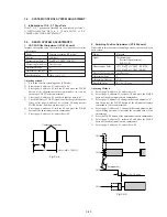
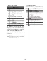
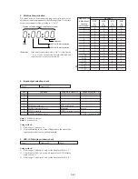
2. IR Video Deviation Adjustment (VC-234 board)
Mode
Camera standby
Subject
Arbitrary
Measurement Point
VIDEO OUT terminal of IR receiver jig
(Terminated at 75
Ω
)
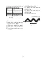
Measuring Instrument
Oscilloscope
Adjustment Page
F
Adjustment Address
7E
Specified Value
A = 0.87 ± 0.04 V
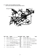
Connection of Equipment
Connect the measuring device as shown in the following figure,
and adjust.
Fig. 5-3-15.
Adjusting method:
1)
Select page: 0, address: 01, and set data: 01.
2)
Select page: 2, address: 01, set data: 39, and press the PAUSE
button of the adjustment remote commander.
3)
Select page: F, address: 7E, and change the data, set the video
signal amplitude (A) to the specified value.
4)
Press the PAUSE button of the adjustment remote commander.
5)
Select page: 2, address: 01, set data: 00, and press the PAUSE
button of the adjustment remote commander.
6)
Select page: 0, address: 01, and set data: 00.
Main unit
IR receiver jig
Pin
5
of
CN003
Frequency counter
Main unit
IR receiver jig
VIDEO
OUT
75
Ω
75
Ω
(1-247-804-11)
Oscilloscope
A
H
Fig. 5-3-16.
Summary of Contents for CCD-TRV67 - Video Camera Recorder 8mm
Page 12: ...1 2 ...
Page 13: ...1 3 ...
Page 14: ...1 4 ...
Page 15: ...1 5 ...
Page 16: ...1 6 ...
Page 17: ...1 7 ...
Page 18: ...1 8 ...
Page 19: ...1 9 ...
Page 20: ...1 10 ...
Page 21: ...1 11 ...
Page 22: ...1 12 ...
Page 23: ...1 13 ...
Page 24: ...1 14 ...
Page 25: ...1 15 ...
Page 26: ...1 16 ...
Page 27: ...1 17 ...
Page 28: ...1 18 ...
Page 29: ...1 19 ...
Page 30: ...1 20E ...


