


5-29
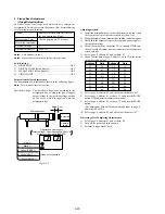
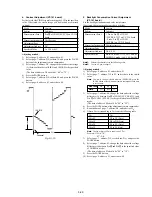
4. Contrast Adjustment (VF-141 board)
Set the level of the VIDEO signal for driving the LCD to the specified
value. If deviated, the screen image will be blackish or saturated
(whitish).
Mode
Camera
Subject
Arbitrary
Measurement Point
Pin
qh
of CN982 (EVF VG) on VC-234
board
Measuring Instrument
Oscilloscope
Adjustment Page
7
Adjustment Address
DC
Specified Value
A=2.20
±
0.1V
Adjusting method:
1)
Select page: 0, address: 01, and set data: 01.
2)
Select page: 7, address: DE, set data: 10, and press the PAUSE
button of the adjustment remote commander.
3)
Select page: 7, address: DC, change the data and set the voltage
(A) between the pedestal (0 IRE) and 100 IRE to the specified
value.
(The data of address: DC should be “00” to “7F”.)
4)
Press the PAUSE button.
5)
Select page: 7, address: DE, set data: 90, and press the PAUSE
button.
6)
Select page: 0, address: 01, and set data: 00.
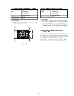
5. Backlight Consumption Current Adjustment
(VF-141 board)
Set the backlight luminance and color temperature.
If deviated, the image may become dark or bright.
Mode
Camera
Subject
Arbitrary
Measurement Point
+ Probe: Pin
qf
of CN982
(EVF BL 4.75V) on VC-234 board
– Probe: Pin
qd
of CN982
(EVF BL) on VC-234 board
Measuring Instrument
Digital voltmeter
Adjustment Page
7
Adjustment Address
DF, E0, E1
Specified Value
BRIGHT mode : A=15.5
±
1.0mVdc
NORMAL mode : A=9.5
±
1.0mVdc
Note1:
Perform the adjustment in the following order.
Note2:
Use the AC power adaptor.
Adjusting method:
1)
Select page: 0, address: 01, and set data: 01.
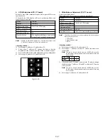
2)
Select page: 7, address: DF to E1, and set data to the initial
value.
Note:
To write in the non-volatile memory (EEPROM), press the
PAUSE button of the adjustment remote commander each time
to set the data.
3)
Select page: 7, address: E0, change the data and set the voltage
difference (A) between Pin
qf
of CN982 (EVF BL 4.75V) and
Pin
qd
of CN982 (EVF BL) to the specified value of BRIGHT
mode.
(The data of address: E0 should be “00” to “3F”.)
4)
Press the PAUSE button of the adjustment remote commander.
5)
Read the data of page: 7, address: E0, and take it as D
E0
.
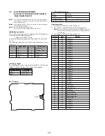
6)
Obtain D
DF
corresponding to D
E0
from the following table.
Note:
The lower digit of D
DF
is equal to it of D
E0
.
Example: If D
E0
is “1B”.
D
DF
= DB
7)
Select page: 7, address: DF, set the data: D
DF
, and press the
PAUSE button.
8)
Select page: 7, address: E1, change the data and set the voltage
difference (A) between Pin
qf
and Pin
qd
to the specified value
of NORMAL mode..
(The data of address: E1 should be “00” to “1F”.)
9)
Press the PAUSE button.
10) Select page: 0, address: 01, and set data: 00.
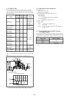
Fig. 5-1-15.
100 IRE
Pedestal
A
2H
D
E0
00 to 0F
10 to 1F
20 to 2F
30 to 3F
D
DF
C0 to CF (Note)
D0 to DF (Note)
E0 to EF (Note)
F0 to FF (Note)
Address
Data
DF
CA
E0
0A
E1
13
Summary of Contents for CCD-TRV67 - Video Camera Recorder 8mm
Page 12: ...1 2 ...
Page 13: ...1 3 ...
Page 14: ...1 4 ...
Page 15: ...1 5 ...
Page 16: ...1 6 ...
Page 17: ...1 7 ...
Page 18: ...1 8 ...
Page 19: ...1 9 ...
Page 20: ...1 10 ...
Page 21: ...1 11 ...
Page 22: ...1 12 ...
Page 23: ...1 13 ...
Page 24: ...1 14 ...
Page 25: ...1 15 ...
Page 26: ...1 16 ...
Page 27: ...1 17 ...
Page 28: ...1 18 ...
Page 29: ...1 19 ...
Page 30: ...1 20E ...


