


81
Chapter 7 Location and Function of Parts and Controls
BVP-E10 Series Product Information Manual
connected to this connector. The selected input
connector number is supplied from this connector.
o
o
o
o
~AC IN (AC power input) connector
Connect to an AC power source using the supplied AC
power cord. The power cord can be fixed to the VCS-
700 using the supplied plug holder.
7-10.
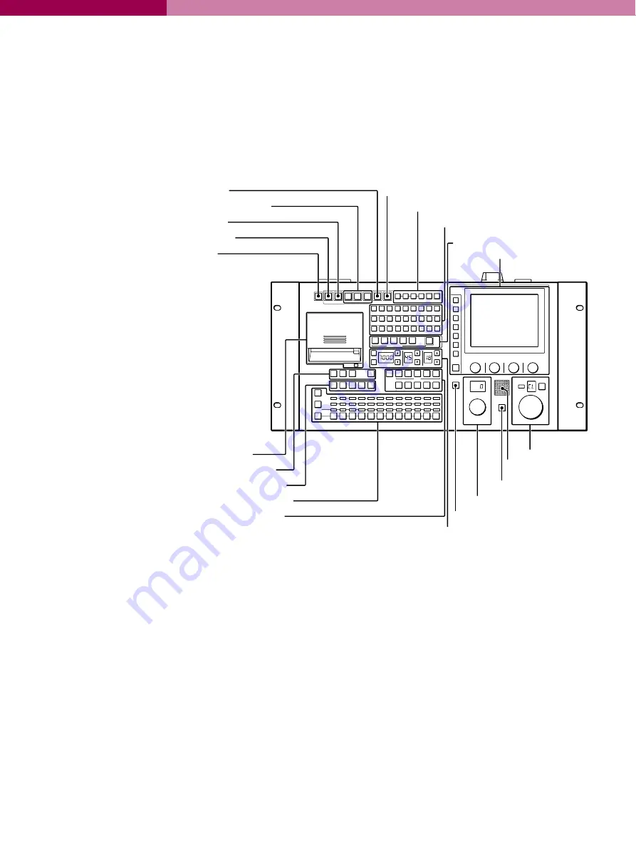
MSU-700A, Master Setup Unit
7-10-1
Operation Panel
a
a
a
a
ALL button
Press the button so it starts flashing to activate the 13
buttons located at the right (from CAM PW to AUTO
SETUP) for all the connected cameras of the same
group.
b
b
b
b
CAM PW (camera power) button
Press and light up this button to turn the power supply
to the video camera ON. (The button promptly flashes
until the camera becomes ready for transmission.)
When you press this button again, it starts flashing and
the power supply to the camera is turned off.
c
c
c
c
VF PW (viewfinder power) button
BVP-900/P cameras only: Press and light up this
button to turn the power supply to the viewfinder ON.
When you press the button again, it goes dark and the
power supply is turned off.
d
d
d
d
Signal output select buttons
Press and light up one of these buttons to activate the
test signal generator of the video camera and send the
respective signals.
TEST 1:
To send a sawtooth signal to test the video
circuits
TEST 2
: To send a staircase signal
BARS: To send a colour bar signal
Note
:
The BARS button takes priority to the other two
buttons. If the BARS button is lit, press the button to
turn it dark before pressing the TEST 1 or TEST 2
button.
e
e
e
e
CLOSE (iris close) button
Press and light the button to close the iris. Press again
to release the close mode.
f
f
f
f
STANDARD button
When you press this button, the video camera is
initialized to its standard state and the button remains
illuminated for several seconds. If you press the button
during this time, the video camera returns to the state
before the button was lit.
For details, refer to the System Manual.
1
1
2
3
4
5
6
7
8
9
10
11
12
2
3
4
5
1
2
3
4
5
A
B
C
D
E
R
G
B
ENC
R
G
B
SEQ
ENC
ON
ECS
AUTO SETUP
MODE
KNEE
OFF
DETAIL
OFF
LVLDEP
OFF
GAMMA
OFF
CHROMA
OFF
SKIN DTL
AUTO HUE
LEVEL
ALL
CLOSE
STANDARD
CAM PW
VF PW
TEST1
TEST2
BARS
START/
BREAK
WHITE
BLACK
MULTI
CARD
CONFIGURATION
MAINTENANCE
FILE
PAINT
MATRIX
OFF
KNEE
APARTURE
KNEE
SAT
MONO
COLOR
COLOR
CORRECT
5600K
AUTO
KNEE
SKIN
DETAIL
DETAIL
GATE
SATURATION CONTRAST
CHARACTER
BLACK
GAMMA
ECS/SHUTTER
PICTURE MONITOR
ACCESS
PARA
PANEL
ACTIVE
EXPAND
WAVEFORM MONITOR
ND
CC
FILTER CTRL
MULTI
TALLY
STORE
SCENE FILES
GAMMA
MASTER GAIN
MASTER BLACK
IRIS
IRIS/MB
ACTIVE
CALL
AUTO
EXT
1
ALL button
2
CAM PW button
3
VF PW button
4
Signal output select buttons
5
CLOSE button
6
STANDARD button
7
AUTO SETUP block
8
Camera/CCU function ON/OFF buttons
9
Scene file control block
q;
Menu operation block
qa
IC card insertion block
qs
PICTURE MONITOR buttons
qd
WAVEFORM MONITOR buttons
qf
Camera select block
qg
Filter control block
qh
ECS/Shutter control block (left)
Gamma control block (center)
Master gain control block (right)
qj
IRIS/MB ACTIVE button
qk
MASTER BLACK control block
ql
CALL button
w;
Camera number/
tally indication window
wa
Iris control block
Summary of Contents for BVP-E10 Series
Page 1: ...Studio OB EFP Camera Family BVP E10 Series Product Information Manual ...
Page 8: ......
Page 16: ......
Page 17: ...BVP E10 Series Product Information Manual 1 2 A Total System ...
Page 40: ......
Page 41: ...BVP E10 Series Product Information Manual 1 4 Control System ...
Page 51: ...BVP E10 Series Product Information Manual 1 5 Optical Fibre Transmission System ...
Page 54: ......
Page 55: ...BVP E10 Series Product Information Manual 1 6 A Quick Lesson on Camera Settings ...
Page 57: ...BVP E10 Series Product Information Manual 1 7 Location and Function of Parts and Controls ...
Page 119: ...BVP E10 Series Product Information Manual 1 8 Menu Settings ...
Page 134: ......
Page 135: ...BVP E10 Series Product Information Manual 1 9 Connector Pin Assignment ...
Page 164: ......
Page 165: ...BVP E10 Series Product Information Manual 1 10 Glossary Terms and Definitions ...
Page 171: ...BVP E10 Series Product Information Manual 1 11 Specifications ...
Page 190: ......
Page 191: ...BVP E10 Series Product Information Manual 1 Appendix ...
Page 203: ......
Page 204: ......


