


Chapter 8 Menu Settings
BVP-E10 Series Product Information Manual
8
124
4.
Select the control mode.
SUPERVISOR MSU mode
: To control all the
cameras connected to all the CNUs (Camera
Network Unit) in the same system.
LOCAL MSU mode
: To control only the
cameras connected to the same CNU (Camera
Network Unit) as the MSU-700A/750 being
operated.
Move the cursor to the required position and press
[Set]
on the MSU Assignment menu to switch
between modes. 5. Select the camera group to be
set.
In LOCAL MSU mode, only the group of cameras 1
through 12 (standard) can be selected. When the
SUPERVISOR mode is active, you can select each
camera group in the system from the lower rows on
the character display of the CNU-700.
Pressing
[Set]
on the MSU Assignment menu with
the cursor on
[NEXT]
calls up the setting display for
the selected camera group.
5.
Select the control functions for each camera.
Camera Select
: Selection by the corresponding
camera select button on the MSU-700A/750
Active/Para
: Control from the MSU-700A/750 in
Panel Active/Parallel mode.
Each item is on (selection/control enabled) when
the characters are shown in black, and off
(selection/control disabled) when the characters
are shown in white. Each time [Set] is pressed on
the MSU Assignment menu with the cursor on the
item turns it on or off.
Caution
Be sure to enable the camera selection for at least
one camera. If selection/control is disabled for all
the connected cameras, the MSU-700A/750
becomes inoperative and the MSU Assignment
mode can no longer be selected. If this occurs,
change the MSU assignment as described in "To
restore operations of the MSU-700A/750" on the
next page.
To resume the initial assignment
Press
[Default]
on the MSU Assignment menu.
6.
When your settings are completed, press
[Set]
on
the MSU Assignment menu with the cursor on
[Ret]
in the upper right of the CNU character display. (To
cancel the settings, press
[Cancel]
.) The character
display of the CNU-700 returns to its previous
status (MSU Assignment display). In SUPERVISOR
MSU mode, perform the settings for the cameras of
other groups in the same manner.
When the MSU assignment is completed
Press [Exit] on the MSU Assignment menu.
8-1-3-1
To restore operations of the MSU-
700A/750
If the MSU-700A/750 has become inoperative by
disabling the selection/control for all the connected
cameras, change the MSU assignment using the
internal switches of the CNU-700 as follows:
1.
Set the MODE switch to 3.
The message "MSU Assignment" appears on the
screen.
2.
Push the SET/CANCEL switch (S6) toward SET.
The same MSU Assignment display as that in step 3 on
the previous page appears. Each press of the UP/
DOWN switch (S5) toward DOWN moves the cursor on
the display to the right, or down when it reaches the
right edge of the frame. Each press of the switch
toward UP moves the cursor to the left, or up when it
reaches the left edge of the frame.
3.
Move the cursor to the desired position, then push
the SET/CANCEL switch (S6) toward SET.
4.
Repeatedly push the UP/DOWN switch (S5) toward
UP until the cursor reaches the SAVE position
outside the frame.
5.
Push the SET/CANCEL switch (S6) towards SET.
The assignment set in steps
3
and
4
is written to
nonvolatile memory.
6.
Return the MODE switch to 0.
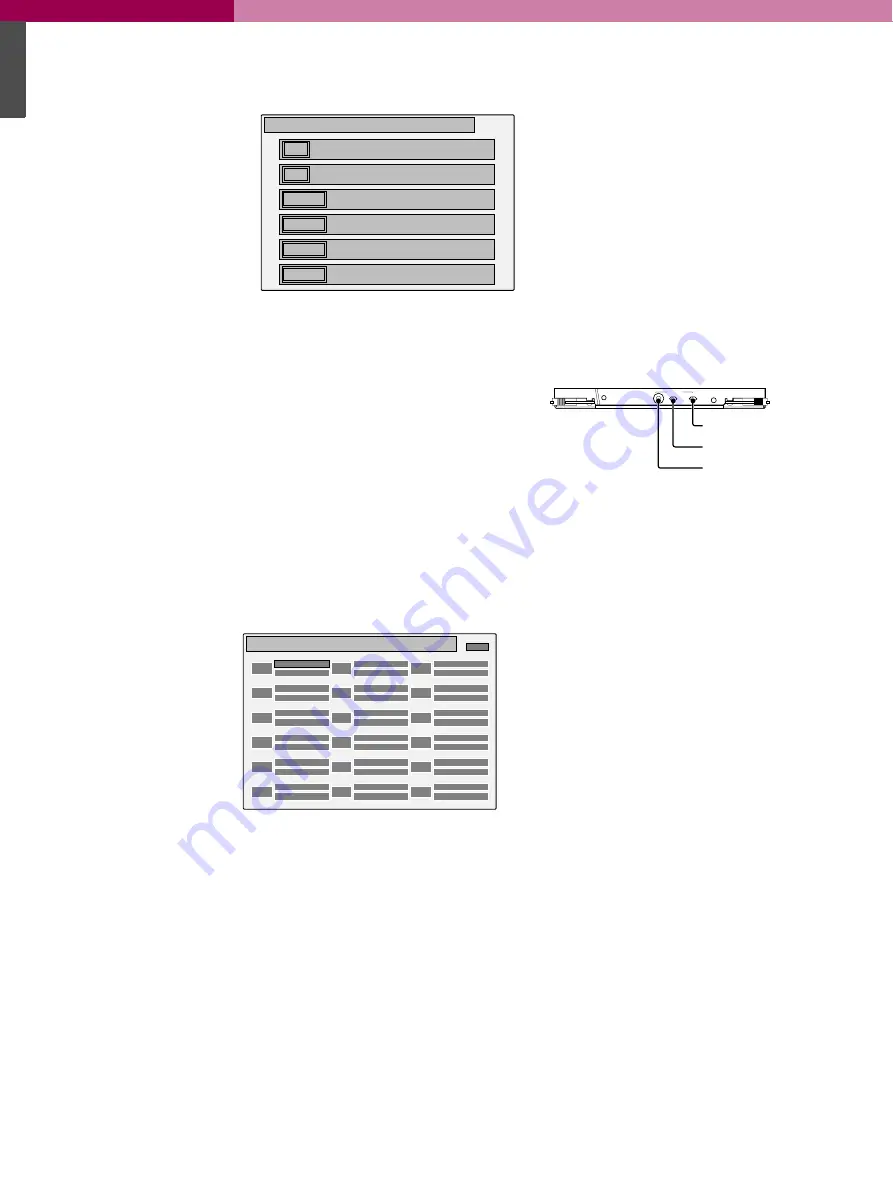
OFF
MSU assignment
ON
NEXT
SUPERVISER MSU mode
LOCAL MSU mode
1 - 6 CAMERA SELECT
7 - 12 /ACTIVE assignment
– – – –
– – – –
– – – –
Character display of the CNU-700 (in MSU Assignment mode
1CAM
MSU assignment [LOCAL]
Camera Select
Active/Para
7CAM
Camera Select
Active/Para
2CAM
Camera Select
Active/Para
8CAM
Camera Select
Active/Para
3CAM
Camera Select
Active/Para
9CAM
Camera Select
Active/Para
4CAM
Camera Select
Active/Para
10CAM
Camera Select
Active/Para
5CAM
Camera Select
Active/Para
11CAM
Camera Select
Active/Para
6CAM
Camera Select
Active/Para
12CAM
Camera Select
Active/Para
Ret
Example: Setting display in LOCAL MSU mode
+5
MODE
CHARACTER
PHASE
UP
DOWN SET CANCEL
AT
SET/CANCEL switch
UP/DOWN switch
MODE switch
Summary of Contents for BVP-E10 Series
Page 1: ...Studio OB EFP Camera Family BVP E10 Series Product Information Manual ...
Page 8: ......
Page 16: ......
Page 17: ...BVP E10 Series Product Information Manual 1 2 A Total System ...
Page 40: ......
Page 41: ...BVP E10 Series Product Information Manual 1 4 Control System ...
Page 51: ...BVP E10 Series Product Information Manual 1 5 Optical Fibre Transmission System ...
Page 54: ......
Page 55: ...BVP E10 Series Product Information Manual 1 6 A Quick Lesson on Camera Settings ...
Page 57: ...BVP E10 Series Product Information Manual 1 7 Location and Function of Parts and Controls ...
Page 119: ...BVP E10 Series Product Information Manual 1 8 Menu Settings ...
Page 134: ......
Page 135: ...BVP E10 Series Product Information Manual 1 9 Connector Pin Assignment ...
Page 164: ......
Page 165: ...BVP E10 Series Product Information Manual 1 10 Glossary Terms and Definitions ...
Page 171: ...BVP E10 Series Product Information Manual 1 11 Specifications ...
Page 190: ......
Page 191: ...BVP E10 Series Product Information Manual 1 Appendix ...
Page 203: ......
Page 204: ......


