


16
Phone In 6 User Handbook
4
REMOTE CONTROL PANEL
REMO
TE C
ONTR
OL P
ANEL
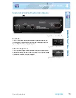
Remote Control Panel Rear Inputs & Outputs
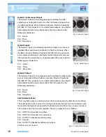
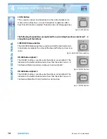
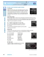
Local Headset
There are 2 x 3.5mm jack sockets provided for connecting a local
headset (separate microphone input and headphones output) for
answering and making calls. The headset is usually used in Call
Screening Mode. The headset signals are balanced electgronically
in the RCP and passed to the BC via the ‘LINK TO BASE CONSOLE’
connector.
Link To Base Console
This 8-way RJ45 socket is used to connect the Remote Control Panel to the Base Console.
The cable between them carries the analogue balanced line level send and receive audio
from and to the local headset. You can use a standard CAT5 cable to link the two units
together. The pin assignments are as follows:
Pin 1 : OUTPUT: Sending headset mic signal, phase
Pin 2 : OUTPUT: Sending headset mic signal, non-phase
Pin 3 : INPUT: Receiving headset earphone signal, phase
Pin 4: Ground
Pin 6 : INPUT: Receiving headset earphone signal, non-phase
All other pins are unused.
Ethernet Port
The 8-way RJ45 socket connector carries a standard Ethernet interface and allows
connection to a local area network. The pin assignments are as follows:
Pin 1 : Transmit data+
WHITE/Orange
Pin 2 : Transmit data-
ORANGE/White
Pin 3 : Receive data+
WHITE/Green
Pin 4: None
BLUE/White
Pin 5: None
WHITE/Blue
Pin 6 : Receive data-
GREEN/White
Pin 7: None
WHITE/Brown
Pin 8: None
BROWN/White
IEC Mains Input
The power supply is connected via an IEC Connector
(CEE22) 85 - 264VAC, 47-63Hz, 10W average.
Fig 4-11: Local Headset
Fig 4-12: Link To Base Console
Fig 4-13: Ethernet Port
Fig 4-14: IEC Power Connector


