8
Phone In 6 User Handbook
3
B
ASE C
ONSOLE
BASE CONSOLE
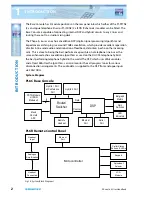
Phone In 6 Base Console Front Panel Controls & Indicators
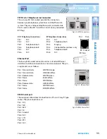
The Phone In 6 Base Console is a 1U rackmount unit to which the audio & telephone
connections are made & which houses the two digital telephone hybrids.
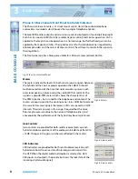
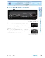
The level of the caller outputs and mix-minus send are displayed on four 8-digit bargraphs.
Each has 2 associated LEDs for AGC (automatic gain control) and Limiter operation. AGC is
applied to the levels to ensure operation in a normal range, but further fixed gain can be
applied by front panel switches. The signal level sent to the telephone line is regulated by
telecom providers and the unit at all times controls the call level to maintain the signals to
their legal limits.
The front panel also has a blue power indicator LED and a recessed reset button.
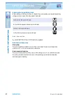
Fig 3-1: Base Console Front Panel
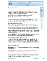
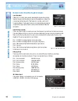
Meters
The meters indicate the levels for both send & receive signals between
the hybrid and the line. For proper operation the 0dB LED should
be illuminated most of the time that normal audio is present, with
occasional peaks just illuminating the +6dB LED (first red LED). The
signal is a pseudo-PPM meter which shares the characteristics of
the PPM dynamics, but is tuned for the telephone environment. The
meters are equi-spaced in the working zone (-6 to +9dB) but to extend
the scale for low-level signals the lowest 2 LEDs are spaced on 12dB
intervals. The unit can work in this range if required but the noise
floor may be excessive (due to the nature of telephone lines) and
consequently the performance of the hybrid may be compromised.
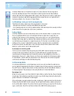
Gain Controls
Gain controls are provided for both send & receive levels on each
hybrid and allow adjustment of the audio gain in 6dB steps from 0 to
+12dB. Changes in the gain switches are reflected in the meters.
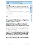
LED Indicators
LED Indicators are provided for both send & receive levels on each
hybrid and show the active state of internal gain controls within
the DSP. When the digital audio build option is selected (i.e. AES/
EBU inputs and outputs), the panel also shows the lock state of the
incoming digital audio signals.
Fig 3-2: Meters
Fig 3-3: Gain Controls
Fig 3-4: Gain Controls

