


12
Phone In 6 User Handbook
3
B
ASE C
ONSOLE
BASE CONSOLE
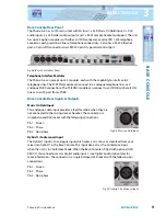
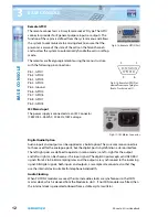
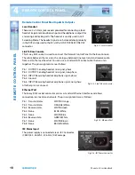
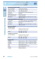
Remote GPI/O
The remote connector is a 9-way female socket ‘D’ type. The GPIO
connector provides for 8 general-purpose inputs or outputs. The
function of these pins is defined from the system menu and allows
the system to communicate to a mixing desk to ensure that the
presenter is aware of the state of the calls on the Telco channels
and to allow the system to automatically handle the calls in self-op
mode.
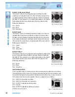
The remotes are freely programmable using the menu structure,
with the following pin connections.
Pin 1: GPIO 1
Pin 2: GPIO 2
Pin 3: GPIO 3
Pin 4: GPIO 4
Pin 5: Ground
Pin 6: GPIO 5
Pin 7: GPIO 6
Pin 8: GPIO 7
Pin 9: GPIO 8
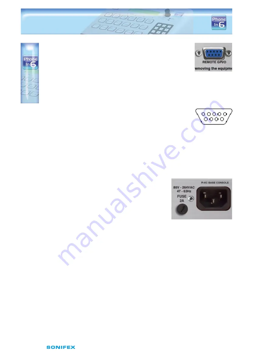
IEC Mains Input
The power supply is connected via an IEC Connector
(CEE22) 85 - 264VAC, 47-63Hz, 10W average.
Digital Audio Option
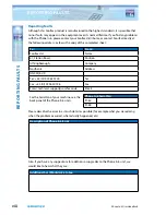
Audio inputs and outputs can be supplied as a build option. They use common connectors
to those used for the analogue ports, but the digital port is by definition a stereo interface.
The left right pairs are defined to operate in mono mode (i.e. left = right for the output
and left or right can be chosen as the input signal). The digital input accepts valid AES/EBU
signals from 32 to 96 kHz sampling rates and the outputs are synchronised to the incoming
signal. All digital signals, both inputs and outputs, are sample rate converted so that they
use the internal clocks suitable for telephone bandwidth.
Audio Clocking
When PI-ISDN2 modules are used, the internal audio clocks are synchronous to the ISDN
master clock, which is derived from the Module in slot 1. If no ISDN modules are fitted, then
the internal clock is generated onboard from a stable crystal oscillator.
Fig 3-15: Remote GPI/O Port
1
5
9
6
Fig 3-16: Remote GPI/O Pins
viewed from rear of plug (or
front of socket on unit)
Fig 3-17: IEC Mains Connector


