background image

28

Radian Motion Sensor 

User Manual

Document Ref: UM-8041-C1

Issue: C - Rev 1

© Sonardyne International Limited 2007

Note

This display may be useful to visualise how the vehicle is moving, but it does not 
present the actual measurements of attitude to you.

If you intend to use the 3D Attitude display, you should have the Attitude Display 
open at the same time.

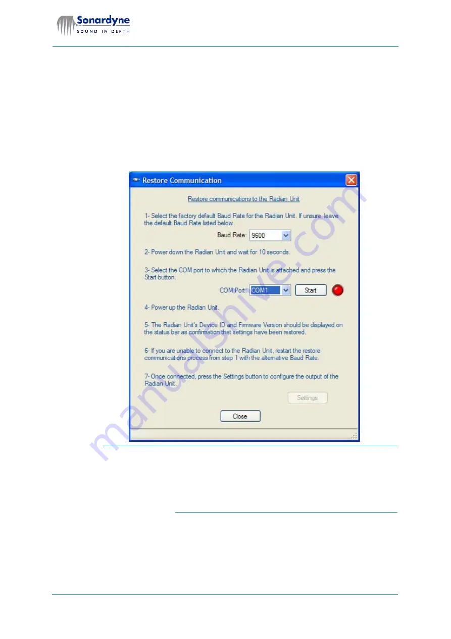
5.5 Communication Failure

If you lose communication between the controlling PC and Radian select 

Options 

> Restore communications

 from the menu bar to display the 

Restore Commu-

nications

 dialog.

Fig 21 Restore Communication dialog

If you lose communication with Radian because you have changed the 
baud rate to be unsuitable for the cable in use, you may have to use a short 
cable suitable for use at 115200 baud to connect the controlling PC to Ra-
dian. You will then be able to recover communications and reset the baud 
rate to be more suitable for the cable in use. Note that the procedure uses 
115200 baud as the factory default setting to recover communications.

Follow the guidance and use this display to try to restore communications with 
Radian.

Summary of Contents for UM-8041-C1

Page 1: ...l Limited Blackbushe Business Park Yateley Hampshire GU46 6GD United Kingdom T 44 0 1252 872288 F 44 0 1252 876100 E support sonardyne com www sonardyne com QUALITY MANAGEMENT CERTIFIED UM 8041 C1 System Manual for Radian Motion Sensor ...

Page 2: ... Bookmarks 2 Links 2 Slider control 3 Search 3 Printing 3 2 Radian Overview 4 Introduction 4 Description 4 Depth rating 5 Applications 5 Communications 5 Magnetic calibration 5 Precautions 5 Shock and vibration 5 Magnetic fields 6 Electrostatic discharge 6 Specifications 6 Communication and physical 6 Electrical 6 Performance 7 Warranty 7 Contact Details 7 3 Quick Start Guide 8 Introduction 8 Desc...

Page 3: ...5 Operation 17 Introduction 17 Power on Radian 17 Software Operation 17 Purpose 17 Operation 17 Procedure 18 Graphical displays 26 Communication Failure 28 6 Magnetic Calibration 29 Introduction 29 Calibration 29 Procedure 29 Troubleshooting 33 7 Data Output Formats 34 Introduction 34 Industry standard 34 NMEA 0183 34 Industry Standard Formats 34 Simrad EM1000 34 TSS2 35 NMEA 0183 Data Formats 36 ...

Page 4: ...b 21 Fig 13 Radian Tool dialog showing the Telegram Mode tab 22 Fig 14 Settings dialog with Display Mode selected 23 Fig 15 Radian Tool dialog when operating in Display Mode 23 Fig 16 Advanced Settings dialog 24 Fig 17 Configure Telegram Output 1 and Output 2 25 Fig 18 Attitude display in Heading up mode 26 Fig 19 Attitude display in North up mode 27 Fig 20 3D Attitude display options 27 Fig 21 Re...

Page 5: ...national Limited 2007 List of Tables Table 1 Document information v Table 2 Document history v Table 3 Communication and Physical specifications 6 Table 4 Electrical specifications 6 Table 5 Data format specifications 6 Table 6 Performance specifications 7 Table 7 Connector pin functions 15 ...

Page 6: ...on Document Title Radian Motion Sensor Document Reference ISSUE ISSUE DATE UM 8041 000 A Rev 1 1 Nov 2006 UM 8041 000 B Rev 1 2 May 2007 UM 8041 C1 C Rev 1 18 Sept 2008 Table 2 Document history Issue Rev Date Comments Section Page A 0 First issue All All B 1 May 2007 CN 9427 Changes to software features 5 All C 1 Sept 2008 Changes to software features 5 All ...

Page 7: ... is arranged in a series of sections and appendices each of which cov ers a major topic Section 1 About This Manual begins on page 1 Section 1 is about this manual and explains what it contains who should read it and how to use it Section 1 also explains the conventions used throughout this manual Section 2 Radian Overview begins on page 4 Section 2 explains briefly what Radian is and what it does...

Page 8: ...avigating the manual The electronic version of this manual is a PDF file read using Adobe Acrobat Reader Acrobat Reader provides a number of features to help you navigate through the manual and to find the information you are looking for conveniently You will not be able to use the electronic version of this manual unless the computer on which it is installed has the Adobe Acrobat Reader software ...

Page 9: ... hand side of the display to move forwards and backwards through the pages Search Acrobat Reader includes a powerful facility to find specific words in the text Click the Search button and then type the word that you need to find The software will then display the first occurrence of that word after the current location Hold the Ctrl key and press G to find the next and subsequent occurrences of t...

Page 10: ... also includes some important cautionary notices and precautions that you must read before you unpack and install Radian 2 2 Description Fig 1 Radian AHRS Radian is a versatile Attitude and Heading Reference System AHRS in a small 300m or 3000m depth rated pressure housing suitable for use in surface and sub surface marine applications It uses data supplied by three axis arrays of solid state line...

Page 11: ...rge ferrous structures Once calibrated the resulting compensation table is stored within the device so that output meas urements will require no further correction while operating in the same area Refer to section 6 Magnetic Calibration beginning on page 29 for detailed in structions to calibrate Radian s earth magnetic field sensors 2 3 Precautions Radian is a delicate precision instrument and mu...

Page 12: ...scharge Components inside Radian are susceptible to permanent and irreparable damage from electrostatic discharge and radiation Protect Radian from electrostatic discharges and shield it from any sources of ra diation in use on the vehicle 2 4 Specifications Radian s specifications are subject to Sonardyne s policy of continual product improvement and may change without prior notice Refer to Sonar...

Page 13: ...nd user servicing have been followed 2 6 Contact Details If you are in any doubt about the proper use of equipment that is manufactured or supplied by Sonardyne International Limited contact Sonardyne for advice The contact details are Sonardyne International Limited Blackbushe Business Park Yateley Hampshire GU46 6GD England Telephone 44 0 1252 872288 Fax 44 0 1252 876100 email support sonardyne ...

Page 14: ... quickly as possible Refer to the indicated sections of this manual for more de tailed information about the relevant topics 3 2 Description of Supplied Parts Radian AHRS instrument Fig 2 Radian AHRS instrument The Radian instrument shown in Fig 2 in its 300m depth rated form contains all the accelerometers rate of turn gyros and earth magnetic field sensors together with the supporting electronic...

Page 15: ...ument and its mounting cradle and use the in formation supplied to prepare the installation location Refer to sub section 4 2 Installation Location beginning on page 12 for an explanation of the require ments needed for Radian s installation location Cables Sonardyne supply a standard interface tail for the Radian unit which has a water proof connector for mating to Radian s multiway port This tai...

Page 16: ... and connect the 9 way socket to a serial port on the NCU To enable power to the NCU s Auxiliary Transceiver port authenticate a transceiver via the NCU by us ing any Sonardyne USBL software You can then verify power availability by checking the flashing LED on the serial port you are using when Radian is pow ered on To configure Radian with the required settings and perform a magnetic calibra tio...

Page 17: ...rect by aligning Radian s housing so that it is level with respect to the mounting location and its fore aft axis aligns with the fore aft axis of the vessel or vehicle Refer to section 4 Installation beginning on page 12 for full instructions to in stall Radian 3 5 Software Installation and Operation Simple user software supplied with Radian allows you to configure Radian s set tings and to displ...

Page 18: ... 4 2 Installation Location The location chosen to mount Radian must provide the following It must not exceed Radian s depth rating It must be nominally level with respect to the vessel or vehicle on which Radian is to be installed It must provide protection for Radian so that there is no danger of damage from impact with other equipment or with sub sea structures around which the ROV is working It...

Page 19: ...unting location should be prepared so that when mounted Radian s alignment meets this requirement Depending on the application for which Radian is to be used it may be the case that the attitude measurements may be used to provide motion compensation for external equipment such as sonar imaging systems In these cases Radian must be mounted so that its fore aft port stbd and up down axes align with...

Page 20: ...al ori entation to the normal pitch attitude Radian s roll axis must align with the nominal roll axis on the vehicle and cannot be adjusted Installation drawing Fig 6 Dimensioned installation drawing 4 4 Site Preparation You must use four M5 screws or bolts with shakeproof and plain washers to se cure Radian at the location you have chosen for it Sonardyne does not supply these fixings ...

Page 21: ...orientation and use the four M5 screws or bolts with shakeproof and plain washers to secure it in position 4 5 Electrical connection Connector detail Fig 7 Radian connection port The single 8 way female connec tion port at the forward end of the Radian pressure housing receives power into Radian and passes digital communications out to the receiving equipment See Fig 7 for details of the pin numbe...

Page 22: ...eat or sunlight for extended periods 3 Assemble the connector and screw the connection hand tight only 4 Route the cable from Radian to the receiving equipment or a junction box Ensure the cable is protected against damage along its length and does not snag against other items of equipment Avoid subjecting the cable to sharp bends or points of stress Secure the cable at regular intervals along its...

Page 23: ...upply measurements after you supply power to it through the single connector After power on Radian performs a series of self test routines on its memory and internal circuitry and then begins to supply measurements required by its current configuration The configuration that it uses when it starts to operate is the configuration in effect when powered off previously For a new Radian the starting c...

Page 24: ...e build date You will require this information if you need to call on technical support from Sonardyne The splash screen closes automatically after a short period and the initial software dialog is displayed You can display the splash screen again by using Help About from the menu bar Fig 8 Radian software s splash screen Initial display The initial software dialog displayed when you first launch ...

Page 25: ... connect to Radian when you are not sure which port is used for the connection or if you do not know Radian s current baud rate With this option selected the software scans through the avail able ports and baud rates until it detects a connection with Radian Click Connect to attempt to connect to Radian The Settings Compass and 3D View buttons become active when you establish connection with Radia...

Page 26: ... User Manual Document Ref UM 8041 C1 Issue C Rev 1 Sonardyne International Limited 2007 Fig 10 Radian tool with an active connection Click Device Settings to display the Settings dialog Settings screen Fig 11 Settings dialog ...

Page 27: ...r display mode the Radian Tool can be configured to output many ASCII tel egrams to many ports When outputting multiple telegrams to multiple ports this may reduce the update rate Also note that certain software packages cannot decode tele grams successfully when certain telegram combinations are output at the same time Refer to section 7 Data Output Formats beginning on page 34 for a description ...

Page 28: ...ed the Device Settings dialog described above to select Telegram Mode the Telegram Mode tab will be available on the Radian Tool dialog and will show the string outputs you have selected However if you selected Display Mode on the Settings dialog the Radian Tool dialog will show only the data contained in the internal binary data communica tions The Telegram Mode tab will NOT be available ...

Page 29: ...Issue C Rev 1 Sonardyne International Limited 2007 Note Fig 14 Settings dialog with Display Mode selected The Display Mode allows you to use the Compass and the 3D View graph ical displays described below Fig 15 Radian Tool dialog when operating in Display Mode ...

Page 30: ... or located near Radian The setting you establish here is displayed on the Radian Tool dialog The Baud Rate setting is the new setting for the sensor port and is the setting that you want it to become following a reset If you request a new baud rate the sensor is reset to the new rate The baud rate setting on your PC will then be updated automatically Be very careful not to change the baud rate to...

Page 31: ...ton to display a new tabbed property page Select each of the outputs required configure the serial port and click Apply Removing the output removes the property page Fig 17 Configure Telegram Output 1 and Output 2 Use Radian Begin to use Radian normally for your operation Either disconnect Radian from the PC and re connect it to the receiving equipment to which it will supply measurements continuo...

Page 32: ...al part of the display shows a graphical representation of Radian s roll and pitch angles presented as a bubble display The central cross hairs intersect at zero roll and pitch with range rings representing angles of roll and pitch ex tending outwards from the centre A scale around the outside of the central part of the Attitude display shows the current heading reported by Radian against a radial...

Page 33: ...Attitude display shows a graphical representation of the ROV on which you have installed Radian animated to show the changes in heading roll and pitch angles Click the 3D Attitude button on the Radian Tool dialog to display a 3D Attitude display The default 3D Attitude display always opens with north at the top You can use the and the keys on the keyboard to rotate the display to place a different...

Page 34: ... Options Restore communications from the menu bar to display the Restore Commu nications dialog Fig 21 Restore Communication dialog If you lose communication with Radian because you have changed the baud rate to be unsuitable for the cable in use you may have to use a short cable suitable for use at 115200 baud to connect the controlling PC to Ra dian You will then be able to recover communication...

Page 35: ...dian to measure and compensate for ferromagnetic objects attached to Ra dian The effects of any ferromagnetic objects not rigidly attached to Radian or any constant fields cannot be compensated These static effects are compensated by the magnetic variation which you enter through the Radian Tool Settings di alog The magneto resistive devices used by Radian have a sensitivity from 100mT to 100mT Fo...

Page 36: ...4 Set the baud rate to the preferred rate 115200 5 Click Scan MagField Mapper scans to find Radian 6 Click Next when MagField Mapper finds Radian to display the Select Out put Directory screen Fig 23 Select Output Directory screen 7 Leave the default settings as they are or change them and click Next to dis play the Select Mapping Mode screen ...

Page 37: ... capture screen 10 While continuing to capture data manoeuvre the vessel or vehicle in a small circle for approximately two minutes maintaining a slow but steady speed throughout the manoeuvre You must complete at least one full circle but you should avoid gathering too much data during this operation 11 Click Stop when you have completed the circular manoeuvre MagField Mapper processes the measur...

Page 38: ...st re start the calibration If the calibration has been successful the report will show how successful it has been You can repeat the calibration if you want to try to improve the result If you cannot obtain a better result then you can re process the data file that was saved for the best attempt and then use that This is an option on the first dia log 12 Close the Calibration Report screen 13 If ...

Page 39: ...sets Radian 3 Use the PC s Device Manager to make sure the PC serial communications port is working correctly Select Start Control Panel System Hardware Device Manager to use the Device Manager 4 Make sure that another program is not holding the serial port on the PC If necessary re boot the PC to release the port 5 Try the MagField Mapper program to see whether it has communications with Radian 6...

Page 40: ... 2 s complement numbers each ex pressed as two binary coded digits Notes Motion measurements contained in the data string are in real time valid for the instant when Radian begins to transmit the string The data string has the ability to include heave measurements However Radian does not output heave and this data field will always be zero Positive roll is port side up starboard down Positive pitc...

Page 41: ...ained in the data string are in real time valid for the instant when Radian begins to transmit the string The measurements include ASCII coded decimal values The data string has the ability to include heave measurements in the range 99 99 to 99 99 metres However Radian does not output heave and this data field will always contain zeros Roll and pitch measurements are in the range 99 99 to 99 00 Po...

Page 42: ... available HCHDG format Fig 31 NMEA 0183 HCHDG data format Description The header information includes the mnemonic HDG for Heading Deviation and Variation Notes If either the deviation or the variation parameters have not been configured in Radian the corresponding field in the string will be null as defined in the NMEA 0183 standard The direction of deviation and variation are indicated by E or ...

Page 43: ...d The units for the measurements are degrees the angles are as described below Notes The data string has variable length with leading zeros if magnitude is less than 1 and minus signs added where necessary Positive pitch is bow down stern up Positive roll is port side up starboard down Attitude measurements contained in the data string are in real time valid for the instant when Radian begins to t...

Page 44: ...inning on page 7 for the return address and contact details for Sonar dyne This section of the manual includes basic routine tasks that you should perform to maintain Radian in a good condition 8 2 Routine Maintenance Immediately after you recover Radian from the sea wash it using fresh water to remove any contamination or debris Examine Radian s housing for signs of damage or degradation Check th...

Page 45: ...nsation table 5 configuration initial settings 17 D data formats 34 NMEA HCHDG 36 NMEA HCHDM 37 NMEA PHTRO 37 NMEA PRDID 36 Simrad EM1000 34 TSS2 35 E electrical power requirements 11 electrostatic discharge 6 H handling precautions 5 I installation 9 alignment 11 drawing 14 location 12 planning 12 preparation 12 14 M magnetic calibration 5 29 magnetic field effects 6 manual bookmarks 2 links 2 na...

Page 46: ...imited 2007 N NMEA HCHDG format 36 NMEA HCHDM format 37 NMEA PHTRO format 37 NMEA PRDID format 36 O operation power off 17 power on 17 software 17 P preparation for installation 9 R radiation 6 RS232 5 RS485 5 S Simrad EM1000 format 34 software graphical displays 26 T transportation 5 TSS2 format 35 ...

Reviews: