DMX BOSS
W
i-F
i C
on
tr
oller
Page 4
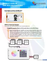
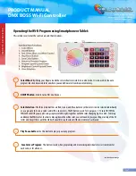
RJ45 Output Location on the DMX Boss:
The RJ45 output location is on the left side of the DMX Boss.
...continued on next page
PRODUCT MANUAL
DMX BOSS Wi-Fi Controller
Toll Free: 866.592.3873
Email: [email protected]
www.SolidApollo.com
Pin1:Data+Pin7:GND
Pin2:Data- Pin8:GND
Learning
Switch
Reset
Switch
12345678
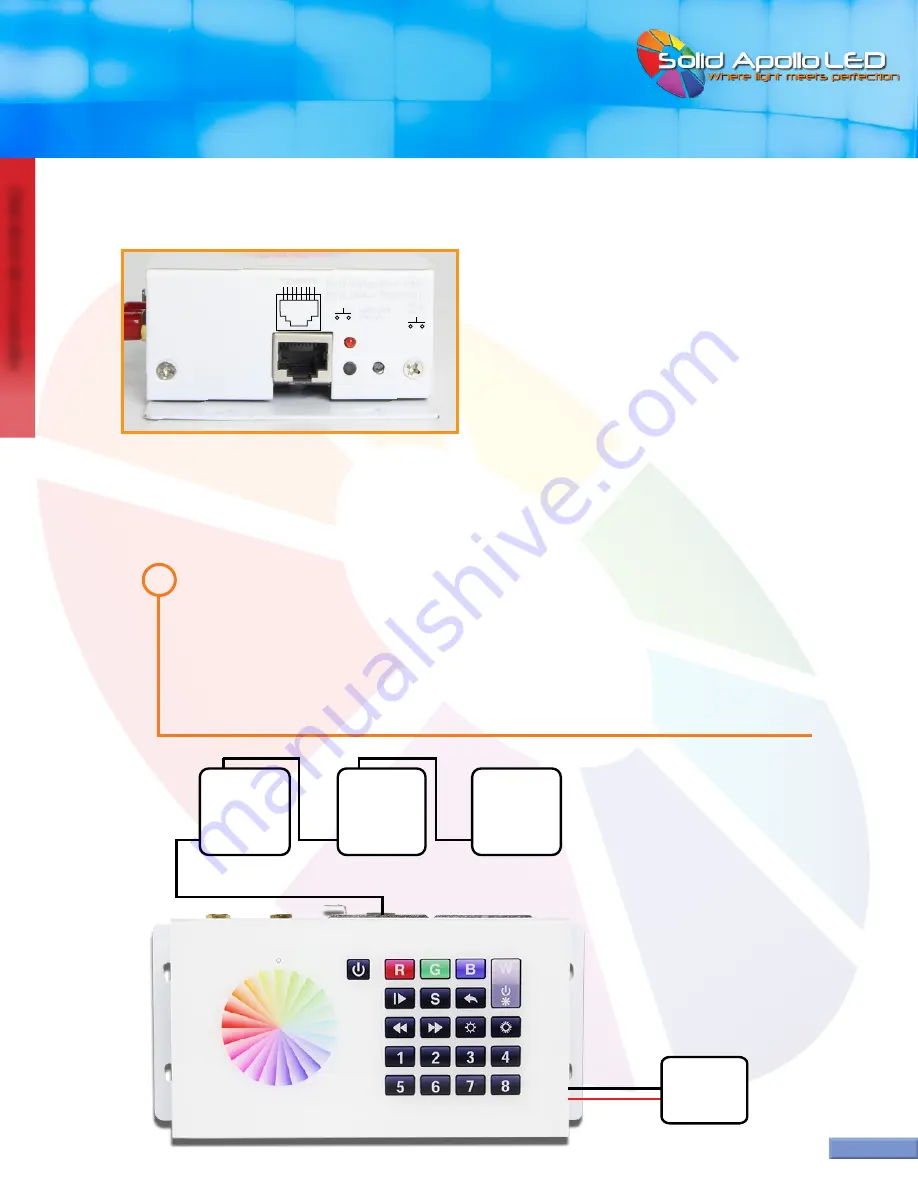
DMX Boss Connection Examples:
This section shows three different ways the DMX Boss can be connected to lighting zones.
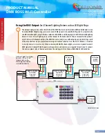
Positive (+)
Negative (-)
XLR Out
XLR Out
XLR In
XLR In
Fixture 1
Channels
1,2,3,4
Fixture 2
Channels
5,6,7,8
Fixture 3
Channels
9,10,11,12
12V Power
Supply
XLR Out
XLR In
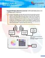
Using XLR Connection Ports:
for DMX enabled fixtures such as Wall Washers
1
Begin by connecting the DMX lights to the DMX Boss by connecting them using the XLR ports on the top of the
DMX Boss. A total of 32 channels are available, for a total of 8 separate lighting zones (4 color channels in each
zone, for colors such as red, green, blue and white). The XLR connections on the lighting fixtures can be connected
in a row. On each lighting zone, set the channel for that zone (refer to the user manual for the products used for
the correct channel numbers). The DMX Boss comes ready to use without pairing or programming as each of the 8
zone buttons are pre-programmed to recognize each zone (button 1 uses the first 4 channels, 1-4, button 2 uses
the next set , 5-8, and so on).


