


Installation and Operation Manual (Rev E)
SGI Series Inverters
DOCR-060371
27
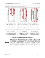
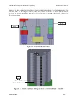
The table below describes the routing path and connection methodology for the optional
neutral conductors that may be connected to the inverter’s transformer to satisfy effective
grounding requirements. The inverter enclosure is designed with a routing path to allow for
proper bending space of these conductors, and therefore the path shown below should be
followed. The transformer’s neutral bar has also been designed with a set of holes to allow for
various field connections such as a box lug or a crimped lug.
SGI 500/PE Neutral Routing Path
SGI 500/500PE Neutral Landing
Location
SGI 500/500PE Alternate Transformer
Neutral Location
SGI 225-300 Neutral Routing Path
SGI 225-300 Neutral Landing Locations
SGI 225-300 Alternate Transformer
Neutral Location
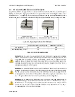
Cu or Al Conductors
Max. 3 x 1/0AWG-400kcmil
75C connections
3 x 1/2” holes, 3 x 3/8” holes
1 connection per hole
Cu or Al Conductors
Max. 2 x 1/0AWG-500kcmil
75C connections
3 x 1/2” holes, 3 x 3/8” holes
1 connection per hole
Table 4.9 – Optional Neutral Routing and Connections


