Installation and Operation Manual (Rev E)
SGI Series Inverters
DOCR-060371
20
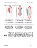
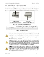
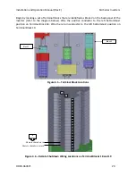
The fused subcombiner plate is populated with a number of fuse holders in a variety of
configurations designed to meet numerous array designs.
SGI 500, 500PE: 8 positions
225 – 400A 600VDC fuses
SGI 225-300: 6 positions
225 – 400A 600VDC fuses
SGI 500, 500PE: 16 positions
110 – 200A 600VDC fuses
SGI 225-300: 12 positions
110 – 200A 600VDC fuses
SGI 500, 500PE: 32 positions
70 – 100A 600VDC fuses
SGI 225-300: 24 positions
70 – 100A 600VDC fuses
Cu or Al Conductors
Max. 16 x 2AWG-300kcmil
75C connections, 275 in-lbs
1-2 wires per fuse position
Cu or Al Conductors
Max. 16 x 2AWG-300kcmil
75C connections, 375 in-lbs
1 wire per fuse position
Cu or Al Conductors
Max. 32 x 6AWG-1/0AWG
75C connections, 100 in-lbs
1 wire per fuse position
Table 4.1 – DC Ungrounded Inputs, Fused Subcombiner
NOTE:
Not all of the fused positions will be used in all designs. In the case that not
all of the positions will be used, the inverter will ship with spare fuses in the
unused locations. The locations of the used and unused positions will be clearly
labeled on the shield that covers the exposed terminals. The installer
must
follow
the labeling for the used connections to ensure proper functionality of the
inverter. Failure to follow the labeling may cause the inverter not to be able to
sense the DC voltage, preventing the inverter from turning on.

