background image


NOTE


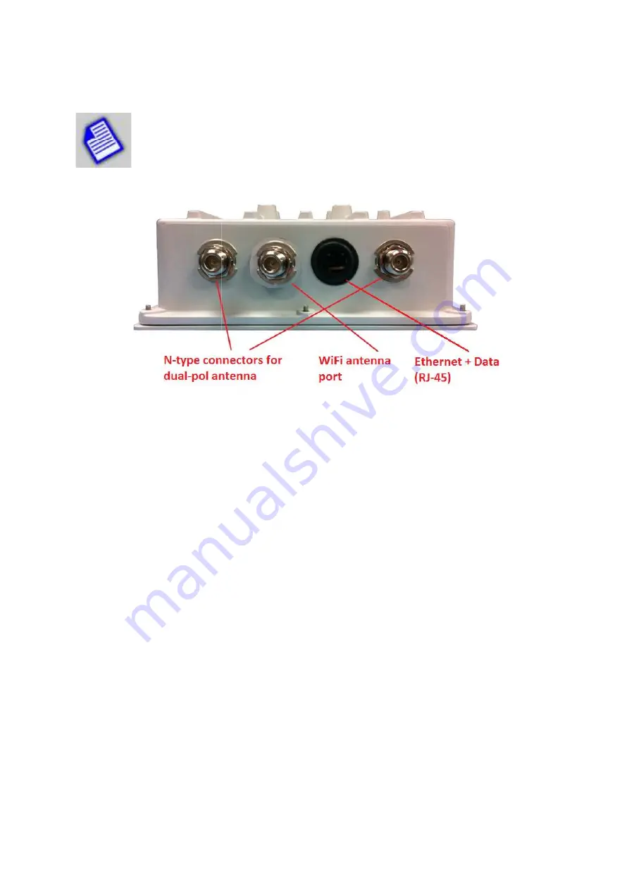
- Make sure to connect the 2.4GHz omni directional antenna to the 

antenna  port 

as shown in the figu

the  same  N-type  ports  at  the  ends.  These  are  for  connections  to  external  5GHz 
antenna for data traffic between radios.   


Once the unit is powered up, you can take any wifi client device (smartphone, tabl
look for the following SSID 


SSID: OFFBAND-xxxxx 


The last five numbers represent the last five digits of the unit serial number so as to distinguish 
among  multiple  units  in the  vicinity.  Once  you  are  connected,  open  a  browser  and  type  in  the 
defalt IP address to access the user interface. 


Default IP address: 192.168.1.100


The WiFi is  enabled  encryption  enabled 
setting, navigate to 

Management 


20 

Make sure to connect the 2.4GHz omni directional antenna to the 

as shown in the figure below. A connectorized

type  ports  at  the  ends.  These  are  for  connections  to  external  5GHz 

antenna for data traffic between radios.    

Once the unit is powered up, you can take  any wifi client device (smartphone, tabl

The last five numbers represent the last five digits of the unit serial number so as to distinguish 
among multiple  units  in the  vicinity.  Once  you  are  connected,  open  a  browser  and  type  in  the 
defalt IP address to access the user interface.  

Default IP address: 192.168.1.100 or 192.168.1.200 

encryption  enabled  as  a  default factory  configuration

Management -> WIFI MGT

 to see the following screen:

Make sure to connect the 2.4GHz omni directional antenna to the 

WiFi 

onnectorized radio units will have 

type  ports  at  the  ends.  These  are  for  connections  to  external  5GHz 


Once the unit is powered up, you can take any wifi client device (smartphone, tablet,  etc) and 

The last five numbers represent the last five digits of the unit serial number so as to distinguish 
among multiple  units  in the  vicinity.  Once  you  are  connected,  open  a  browser  and  type  in  the 

as  a  default factory  configuration. To  change  the Wifi 

owing screen: 

Summary of Contents for ES700

Page 1: ...1 SKYWAY ESSENCE SERIES Point to Point PTP Wireless Kit User Guide ES700 September 2016 Rev 1 2a ...

Page 2: ...for errors contained herein or for incidental or consequential damage in connection with the furnishing performance or use of this document or equipment supplied with it Information to User Any changes or modifications of equipment not expressly approved by the manufacturer could void the user s authority to operate the equipment and the warranty for such equipment Disclaimer In accordance with So...

Page 3: ... Introduction 13 5 2 Ethernet Cable Feedthrough Assembly 14 5 3 Mounting Bracket and Tools 16 5 4 Unit Mounting 16 5 5 Mounting of Separate Antennas 18 5 6 GPS Antenna Mounting 18 6 WiFi Management 19 7 Ethernet Configuration 21 8 Wireless Configuration 23 9 System Properties 29 10 System Access Configuration 31 11 Antenna Alignment 32 12 Spectrum Analysis 34 13 Monitoring Operation 36 14 Software...

Page 4: ...i GUI access GP location service unit location GPS synchronization available as a future software upgrade item Channel BW options of 20 40 and 80 MHz Power over Ethernet PoE for simplified cable routing Integrated antenna radio simplifies installation and eliminates lossy RF coax runs Frame aggregation for enhanced data throughput Line speed QoS packet inspection prioritizes latency sensitive real...

Page 5: ...els ES5723 ES5720 and ES5729 are based on the same wireless radio module The differences are in the antenna gain or use of an external antenna 1 3 Radio Packaging Content The following items are included in each PTP kit package Please contact Solectek Sales if there is any missing item Radio unit 2 POE power supply AC to 48VDC 2 Mast mounting kit 2 Cat5 6 feedthrough gland 2 Coax grommet sealing t...

Page 6: ...Steps This section summarizes the steps needed to properly configure and install the SkyWay Essence Radio As the background and guidelines for much of the radio installation process are well covered in many in depth publications and training classes only those steps that uniquely relate to the SkyWay product are covered in this User Guide A System Design Requirements analysis Site Survey RF System...

Page 7: ...nstallation Unit Mounting Spectrum Analysis Antenna alignment E Verification Link status metrics Ping connectivity Performance testing Reliability monitoring F Optimization RF channel tuning Data rate tuning QoS G Management Maintenance Upgrades Access Methods Tools Diagnostics ...

Page 8: ...s 10 100 1000 Gigabit Ethernet Power Connector 1 WiFi Antenna port N type 2 RF Ports N type female Connectorized PTP unit only The Essence radio interfaces will have additional inte orders hardware options The port configurations for optional features described in separate documents The RJ45 connector is accessed at the bottom of the unit through a multi through If included the RF Ports are access...

Page 9: ...m View Connectorized unit VIEW SMA CONNECTOR FOR GPS ANTENNA S Connecting the SkyWay Unit to Network Use the diagram below as a guide to cable your SkyWay test system using a PC or Laptop cables An auto MDIX feature eliminates the need for cross SHOWN Use the diagram below as a guide to cable your SkyWay test system using a PC or Laptop MDIX feature eliminates the need for cross over ...

Page 10: ...Windows OS Enter the TCP IP setup window of Ethernet adapter properties page Set the IP addresses to the following IP Address Setup on your Computer Ethernet IP Address 192 168 1 1 Subnet Mask 255 255 255 0 Open a Web Browser on the Test PC At the URL line type in the following Type of Unit Default IP Address Slave Unit 192 168 1 100 Master Unit 192 168 1 200 LAVE UNITS in your Windows OS Enter th...

Page 11: ...earance of your GUI will depend on the type and version of your web lease contact Solectek sales and support for detailed The access username is admin and the default password is admin Default Radio Log in Info User Name admin Password admin on the above Windows screen and the Status Overview displayed as shown below Master unit version The details will be reviewed in a later screen may look diffe...

Page 12: ...o radio units in a PTP link share the same Link ID bandwidth data rate and security settings Access Control List ACL is enabled as a factory default setting It is also important to have identified and prepared the antenna RF coax and Cat5e cable solutions that will be used in the intended application Positioning It is important to remember that the SkyWay radio and antenna system generate and tran...

Page 13: ... shared volume or an FTP session on a typical Windows Intel machine is not adequate to accurately measure throughput NOTE Units bench tested in an indoor configuration should not be expected to deliver full rated throughput Benchmarking is typically performed after a system is deployed WARNING When it is not in use all optional ports must be plugged in so that there is no water intrusion damage to...

Page 14: ...ncluded with your SkyWay radio 5 2 Ethernet Cable Feedthrough Assembly Only a single Ethernet cable is needed to connect the SkyWay radio to the indoor PoE Injector Since the cable is exposed to the outdoor elements heat moisture and UV light only outdoor rated shielded Cat5 Ethernet cable should be used To ensure all weather operation the weatherproofing cable feedthrough also known as grommet or...

Page 15: ...ly pushed or pulled Lightly wrench tighten being careful not to overtorque the Compression Nut The unit with properly installed feedthrough appears as follows NOTE Removal of the RJ45 plug from the radio requires a tool such as a thin screwdriver or opened paperclip Care must be taken not to damage the Feedthrough Body or RJ45 plug NOTE The total combined length of the Ethernet cables between the ...

Page 16: ... Tools The following figure shows all components of the mounting kit The installation steps will be shown in the next section Tools necessary for tightening bolts and nuts are 10mm wrench for bolts to fasten the L bracket to the radio enclosure 13mm wrench for nuts to tighten U bolt nuts 5 4 Unit Mounting The final installation step involves mounting your SkyWay radio to an outdoor mast ...

Page 17: ... installation steps bracket on the back of the radio enclosure The hole patterns are symmetric and you can rotate the enclosure by 90 degrees before inst bracket for establishing the radio link with horizontal polarization Using the step bracket and U bolt fasten the L bracket to the mast ate the enclosure assembly in the horizontal direction bracket has a curved groove which can be used to tilt t...

Page 18: ...onnections is essential This process prevents water from entering the chassis or cables through the connectors In order to provide an adequate seal it is advisable to apply three wrappings 1 electrical tape 2 sealant such as the butyl mastic which is provided with the product 3 electrical tape The first wrapping of tape should be a single layer followed by a generous wrap of butyl mastic Finally a...

Page 19: ...on to the sky Some obstructions such as a pole and other items may not be The GPS operation will not be interrupted if at least half of the sky is unobstructed 6 WiFi Management ES700 radios have a built in 2 4GHz Wifi module that can be used for accessing the user interface without Ethernet connection First you will need to connect a 2 4GHz omni directional antenna to the WiFi port N of the unit ...

Page 20: ...ns to external 5GHz antenna for data traffic between radios Once the unit is powered up you can take any wifi client device smartphone tabl The last five numbers represent the last five digits of the unit serial number so as to distinguish among multiple units in the vicinity Once you are connected open a browser and type in the defalt IP address to access the user interface Default IP address 192...

Page 21: ...ault gateway for the local unit 21 enable disable the WiFi user interface If the interface is enabled it is strongly recommended that encryption is enabled to keep the interface secure Configuration Ethernet Configuration to access the following nfiguration IP address of the local unit Subnet mask of the local unit Default gateway for the local unit the WiFi user interface If the interface is enab...

Page 22: ... and Save Apply Reset restores the values before you make any modifications Save make the changes effective but does not write such changes to memory Save Apply writes the changes to memory WARNING Make sure that you keep a record of the IP address information of the unit ...

Page 23: ... remote radio unit Channel Spectrum Width Allows selection of the channel bandwidth BW in MHz of the RF network Allowable options are 20 MHz 40 MHz and 80 MHz If maximizing throughput at shorter distance is of primary importance then larger bandwidth of 40 and 80 MHz may be more appropriate NOTE Both Master and Slave units must be configured with the same Bandwidth setting in order to have the lin...

Page 24: ...h selection is 40 or 80 MHz this 20MHz channel becomes the in adverse RF conditions The following is a diagram of all available channels Allowable channels of operation for outdoor links depend on the country region Allowed channels of operation in the US are Channel 36 40 44 48 5 15 to 5 25 GHz nnels 149 153 157 161 165 5 735 to 5 85 GHz US FCC version of ES700 is factory configured to operate in...

Page 25: ...nting for the time of flight for packet transport over the wireless channel Interface Configuration has two different sections General Setup and Wireless Security Mode In a PTP link one unit has to be designated as Master the other Slave The Master unit control the frequency channel and a few other parameters of operation There is no particular requirement for a particular side to be the Master un...

Page 26: ...e the best TX modulation and MIMO settings based on current RF conditions At power up or reset the ACM function will begin operation at the most robust modulation settings BPSK 1 2 If link conditions warrant higher order settings will be tested and selected for use The ACM function operates continuously i e if RF link conditions change then the modulation and MIMO settings will respond in order to...

Page 27: ...ardless of link distance or RF conditions You can set the RSSI level you want to maintain the link at typically 50dBm and the Tx power from the other side will automatically adjust its Tx power based on the feedback from the remote unit s benefit is to insure the link quality is consistent overtime and guard against using excessive Tx power especially for short links Excessive Tx power is a big fa...

Page 28: ...n WPA PSK WPA2 PSK and WPA PSK WPA2 PSK Mixed Mode The default is No Encryption Cipher This specifies the cipher types The choices are Auto CCMP AES TKIP and CCMP AES Key This is the 128 bit key used for AES encryption The key must match between the Master and Slave units for the link to function properly if encryption is enabled The key length has to be at least 8 characters ...

Page 29: ... current time on the radio unit s time clock The time can be synchronized with the local host computer managing the radio by clicking Sync with local PC word description that the user gives to the radio unit e g e System Name value is completely up to the user and has no effect on System Name can be up to 32 characters long and consist of all wing symbols at sign dash period underscore Name may no...

Page 30: ...P is enabled above the user can enter NTP server tab will show the following screen System log buffer size kiB This defines the log buffer size The default is 16KB The system log can be uploaded to a remote server The user can specify the IP address of the remote log server here erver Port Specify the port number to be used for connecting to the This specify the types of log items to be uploaded t...

Page 31: ...etween the regular HTTP mode or sec value is HTTP The port number to be used for web server The default is 80 When you are using HTTPS mode on the radio unit make sure to start in the URL window of your browser Just typing the IP address may not allow access to the radio GUI It is strongly advised that the admin password be recorded and stored in a secure location Password hint fields are case sen...

Page 32: ...ystem s link capture envelope angle The audible repetition rate will increase as RSSI improves a higher value will cause a faster rate To assist with both coarse and fine tuning the rate is NOT a simple function of RSSI value Rather the rate will continue to increase as long as adjustments deliver an improved RSSI As soon as any degradation alignment overshoot is detected the rate quickly falls re...

Page 33: ... the audio alignment mode will run before it default value of the interval is 30 minutes button next to the interval will start the audio alignment mode the Run button at this point Click the Stop button to stop the alignment nment process is completed Clicking the Launch button activates the spectrum analyzer mode which will be described in the next section The timer for the audio alignment inter...

Page 34: ...ned in the general direction of the target radio NOTE If a noise and interference only analysis is desired do not turn on the remote unit during the spectrum analysis as the presence of the remote unit will affect the sweep data NOTE Enabling a spectrum sweep will disable RF traffic until the scanning process is completed NOTE Fluctuations in RSSI values up to 2 dB should be expected This should b...

Page 35: ...36 to 165 are scanned for RSSI he user can assess which channel would be the cleanest one to be used from the values ease keep in mind that for wider channel operations 40 or 80 MHz you will need several blocks of 20 MHz channels to be relatively clean Refer to the Section 7 for frequency block uses all 20 MHz channels from 36 to 165 are scanned for RSSI he user can assess which channel would be t...

Page 36: ... Overview to monitor the current status of the system as shown below This screen is for status only Navigate to the Configuration screens if sett This screen periodically updates to the current status at every 2 seconds noteworthy items The elapsed time that the unit has been running since the last reboot or power cycle information is found in the upper right corner of the screen to monitor the cu...

Page 37: ... the system is displayed here Clicking on the GPS coordinates will lead to a map of the area with the system location pinpointed This is the current Link ID of the local unit Make sure that the Link ID is the same for the local and remote units of a PTP link It is recommended that the user assign a unique Link ID for each PTP link so that there is no unintended RF association with another PTP link...

Page 38: ...io antenna cable or antenna alignment The user can use this information for diagnostic purposes Noise This is the noise level strength measured by the local receiver It is a measure of the RF noise in the RF path from the remote unit to the local unit Network Section MAC Address This is the Ethernet MAC address of the local unit This is used for identifying the radio in network management Real Tim...

Page 39: ...dwidth It is a weighted average va calculated per packet basis using the following formula where Tmin is the minimum time that a packet would take at the highest rate without retries and Treal is the time such a packet actually took in real life taking into account CCQ would be lowered if an adverse RF channel condition causes packet losses thus retries and the use of lower transmit rates Backup a...

Page 40: ...opy will be stored in the tar file format The user can restore the user configuration database to the factory setting Perform reset button During the factory default operation the radio will not be availab for normal operation Because of the changes in the radio configuration the user will need to reconfigure the radio to the proper setting for the PTP link before a link can be established The use...

Page 41: ...e corruption may occur if power is disrupted during the flash write process System Reboot and Logout to reboot the radio system The following confirmation screen will appear to make sure that the reboot process was not button to reset reboot The reboot process will take approximately is finished the browser refreshed the current page automatically on the menu to log out of the GUI session Similar ...

Page 42: ...2 and the logout process is now completed Log Log displays all major events that may be noteworthy for the system administrator for both monitoring and troubleshooting purposes Clear Log button will erase all even log entries from the memory Diagnostic Tools access to diagnostic tools navigate to Tools Diagnostics menu to view the following Log displays all major events that may be noteworthy for ...

Page 43: ...es and host computers You can ping the remote unit from the unit you are accessing via the user interface A default gateway and DNS server are needed to use these tools with a named target Configuration Ethernet Configuration Status ARP to view the ARP status for both Master unit as shown in the screen below There are additional diagnostic tools to arrange automatic rebooting of the unit periodica...

Page 44: ...t upon detecting that connection to a specified IP address is broken You can specify IP address to Ping Startup Delay sec and Failure Count to Reboot The default In certain situations the user may want to reboot the unit automatically This can ne at a certain time of the day as specified in time or at a given specified time interval e g If enabled Ping Watchdog reboots the radio unit upon detectin...

Page 45: ...ink ID Back_haul Security Open Access Control List ACL Enabled LAN Others IP Address Slave unit IP Address Master unit 192 168 1 100 192 168 1 200 IP Mask 255 255 255 0 IP Gateway 192 168 1 1 Login Name Password admin admin Ethernet Port Auto Web server mode and port HTTP Port 80 Ping Watchdog Disabled Auto Reboot Disabled Audio Antenna Alignment Disabled Audio Alignment Runtime 30 minutes ...

Page 46: ... 5 15 5 25 GHz or 5 725 5 850 GHz frequency bands This product has been certified by the U S Federal Communications Commission for use in the United States of America in that band Other markings on the unit label shall indicate regulatory compliance in other international areas Any prospective user of this product outside the United States of America should prior to such use contact the government...

Page 47: ...persons and must not be co located or operating in conjunction with any other antenna or transmitter For operation in the US under the FCC rules this device has been designed to operate with the antennas listed below and having a maximum gain of 29 dBi Antennas having a gain greater than 29 dBi are prohibited for use with this device The required antenna impedance is 50 ohms This equipment has bee...

Page 48: ...ed except as allowed under the copyright laws Solectek Corporation makes no warranty of any kind with regard to the material contained in this document including but not limited to the implied warranties or merchantability and fitness for a particular purpose NOTE Changes or modifications not expressly approved by Solectek could void the user s authority to operate the equipment SkyWay and Solecte...

Reviews: