background image


© CASWA Pty Ltd – 2013 


28 | Page 

If the Lockout control is set to a non-zero value, when the indicated load exceeds 
<Overload>+Lockout% a special alert will be sent and the fault output will not close. This effectively 
disables the crane until it can be inspected and put back into service.  

NB:  The locked state can only be cleared by unchecking the “Locked” checkbox. 

An Example: 

Crane capacity: 10t 
Overload set to: 11t 
Lockout set to: 20%


Indicated load 

Liftlog™XL  behaviour 

>=11t  and < 13.3t 

An overload alert is sent, and lifting is disabled 
until the indicated load drops below 11t 

>=13.3t 

An additional locked out alert is sent and lifting is 
disabled until a technician re-enables it by 
clearing the “Locked” checkbox.  


4.10


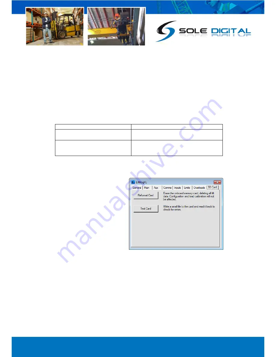
  SD Card Management 

Select the SD Card tab to bring up the 
following screen: 


4.10.1


Test SD Card 

To test the card and verify that the LiftlogXL device it is correctly writing data to, and reading data 
from, its internal SD card, press the <Test Card> button.  

A popup box will appear informing you of whether the Test Passed or Failed. 

If the test fails, it is recommended that the SD card be removed and replaced to ensure it is seated 
securely.  The test process should then be repeated.  If the card fails again, then a reformat may be 
necessary. 

Summary of Contents for Liftlog XL

Page 1: ...Liftlog XL Advanced Crane Data Logger Model LL300 Version 2 0 Installation and User Manual V1 8 07 10 2013 CASWA Pty Ltd 2013...

Page 2: ...4 3 3 5 Connecting Load Sensor Inputs 15 3 3 6 Connecting the Fault Output 17 4 COMMISSIONING DETAILS 18 4 1 Installing and Launching the FSU Application 18 4 1 1 FSU Program Installation 18 4 1 2 Ins...

Page 3: ...Sensitivity 27 4 9 3 Lockout 27 4 10 SD Card Management 28 4 10 1 Test SD Card 28 4 10 2 Reformat SD Card 29 4 11 Running CheckIt Diagnostics 29 4 12 Recording a Service 30 5 ROUTINE MAINTENANCE 31 6...

Page 4: ...ing GSM 3G GPRS or WIFI connectivity Liftlog XL is particularly well suited to users seeking an integrated enterprise solution for crane monitoring and management high risk applications requiring incr...

Page 5: ...ed events 4 Hz Tlog Duration of a logged event 1 30000 Sec 2 2 Physical Specifications Overall length mm 157 Overall width mm 86 Overall height mm 58 Weight kg 0 3 Mounting Screwed or 30mm DIN rail El...

Page 6: ...t impedance of 0 10V input 1500 Ohms I24 24V output current 100 mA Operating temperature 40 85 Note 2 C Notes 1 Power supply ve and GND pins are at chassis GND 0V potential 2 Extended operation at max...

Page 7: ...ting Changing Your SIM Card Remove the lid from the unit by releasing the clips at each end to reveal the internal circuit boards Locate the SIM card socket on the upper circuit board and insert a dat...

Page 8: ...have also been altered slightly Sticker orientations showing terminals for Liftlog XL devices with serial numbers that start with a 2 i e numbers greater than 199 are as follows Figure 2 Version 2 St...

Page 9: ...Connection for MAIN hook to terminal Q F1 or F2 on an ABUS LIS Q Link 8 Connection for MAIN hook to Ground on an ABUS LIS Q Link 9 Drive voltage for 4 20mA sensor 24V 10 Auxiliary inputs 1 3 can be us...

Page 10: ...nection for AUX hook to gnd on an ABUS LIS Q Link 35 Connection for AUX hook to terminal Q F1 or F2 on an ABUS LIS Q Link 36 Drive voltage for 4 20mA sensor 24V 37 Opto isolated limit input can be use...

Page 11: ...er source contact tech caswa com Liftlog XL requires constant power so that it can maintain a connection to the 3G GPRS network Do not connect the unit after the K1 or E Stop relay Doing so will cause...

Page 12: ...remember that when powering the Liftlog XL from a DC source that it may not be possible to use the load limiting functions of the Liftlog XL as the outputs only switch AC LiftlogXL 25 27 0VAC 9 36 24V...

Page 13: ...pins 1 25 27 33 by a set of voltage independent contacts Where spare or auxiliary contacts are not available on the MAIN contactors small relays must be employed For example the DOWN and UP inputs on...

Page 14: ...ss the limit switch or chain of limit switches to be monitored All limit inputs are voltage independent and typically configured to be normally closed i e any voltage across these terminals keep the l...

Page 15: ...connects to pins 28 34 It can also accept wireless inputs for both the MAIN and AUX hooks via HoistNet 3 3 5 1 Strain gauge input When using a strain gauge load cell to measure the load on either the...

Page 16: ...oad Sensor When using a 0 10V signal to monitor the load e g from a Konecranes ControlPro connect the load sensor between pins 1 or any other pin marked GND and 6 for the MAIN hoist and pins 33 and 28...

Page 17: ...nected into the Q Link terminal pin marked 8 or 34 for the MAIN and AUX hoists respectively Connecting a signal for the MAIN hoist is depicted as follows 3 3 6 Connecting the Fault Output The two faul...

Page 18: ...n Ensure that your computer is switched on connected to the internet and that the minimum required software versions are installed see Appendix B for minimum system requirements Ensure that the LINK 2...

Page 19: ...he search Version 2 Liftlog XL devices are differentiated from version 1 devices by a II superimposed over the device icons NB The Bluetooth link between the Laptop using a Link 2 and a Liftlog XL has...

Page 20: ...date firmware at a later time NB If you did not see this window then your device already has the most current firmware 4 4 Checking the Date Time After checking for firmware the FSU application verifi...

Page 21: ...cation entry is set to Storage card and press Save Progress is indicated on the MAIN screen Time to download depends on the number of lifts and can be up to 20 minutes 4 6 Main and Aux Hoist Configura...

Page 22: ...ving a HoistNet Input Liftlog XL devices are now compatible with CASWA HoistNet This means that they can obtain their load signal wirelessly from any other HoistNet enabled device eliminating the need...

Page 23: ...istNet device or to change the bound device press the Bind button on the Load screen and then select Unbind on the popup box 4 6 3 Using the LiftlogXL with a ControlPro If your LiftlogXL device is con...

Page 24: ...less than half of full scale then increase the amplification by moving the gain slider to the right 4 6 5 Calibrating the Logger With no load on the hook press the Zero button After a brief pause the...

Page 25: ...a The values for APN UserID and Password are usually provided by the company supplying the SIM card If the SIM card is provided by CASWA then the settings are APN telstra m2m UserID blank Password bla...

Page 26: ...ng of the unit When a signal is detected the respective box will be checked 4 8 1 Using XL devices with a HVDC IO Expander If you have been supplied a Sole Digital HVDC10 module for installing a Liftl...

Page 27: ...ettings for the behaviour of both Main Aux and Combined overloads 4 9 1 Main Aux and Combined In each of these boxes enter the required overload in tonnes If only one load input is connected it is rec...

Page 28: ...bled until the indicated load drops below 11t 13 3t An additional locked out alert is sent and lifting is disabled until a technician re enables it by clearing the Locked checkbox 4 10 SD Card Managem...

Page 29: ...utton You will be asked to confirm the action 4 11 Running CheckIt Diagnostics To confirm whether critical settings and parameters have been set sensibly after completing the setup and commissioning o...

Page 30: ...the Service tab on the FSU Application Hint You may need to scroll through the tabs to see it Enter the relevant reference number for the work e g from your maintenance management system or job sheet...

Page 31: ...CASWA Pty Ltd 2013 31 Page 5 ROUTINE MAINTENANCE There is no routine maintenance required for this device...

Page 32: ...d at other times to indicate normal operation Illuminates continuously when either hoist exceeds it overload limit 6 2 Accessing Your Data Open a web browser e g Internet Explorer and type in the URL...

Page 33: ...type of events will trigger an automatic email These settings do not affect what data is recorded Service History This shows a list of all service date times and their respective job numbers that hav...

Page 34: ...d indicated Wrong input selected Refer to section 4 6 5 to calibrate the input Load input wired wrong Refer to section 4 6 5 to calibrate the input Insufficient gain Refer to section 4 6 5 to calibrat...

Page 35: ...tween the command and the CR Where numbers are sent or received they are sent as clear text eg 1234 Where a number represents a load eg the o and O commands and the logged data returned by the u comma...

Page 36: ...the actual load See the C and r commands Send c CR Rcv 11 CR C Write Set the cal parameter In normal operation the cal parameter would be set as follows Send the r command to get the raw reading from...

Page 37: ...this are provided in this User Guide B 1 How Much Data When choosing a mobile service plan for use with Liftlog XL select the one with the lowest available monthly data limit A VERY busy crane will g...

Page 38: ...endix C FSU SYSTEM REQUIREMENTS The minimum requirements for operating CASWA s Field Service Utility FSU and Link 2 Bluetooth modem are Laptop computer running Windows XP SP3 or later One Spare USB po...

Page 39: ...Pack 3 Hook 1 main 2 Aux 3 Both hooks 4 Load from load cell other input in tenths of a tonne 5 Duration of motion in tenths of a second 6 Motion code type of motion as shown in the following table Mot...

Reviews: