background image


UPS for 480 Vac Grid, User Guide, doc. rel. 4.0 

162  


To update the full system: 

Select System, see Figure 147.  

Press start to begin the firmware upgrade process.  

Wait as the system runs through the various subsystems and upgrades each with the relevant 
firmware.  


To update the static switch only: 

Select STSW, see Figure 147.  

Press start to begin the firmware upgrade process.  

Wait as the system upgrades the static switch with the relevant firmware.  


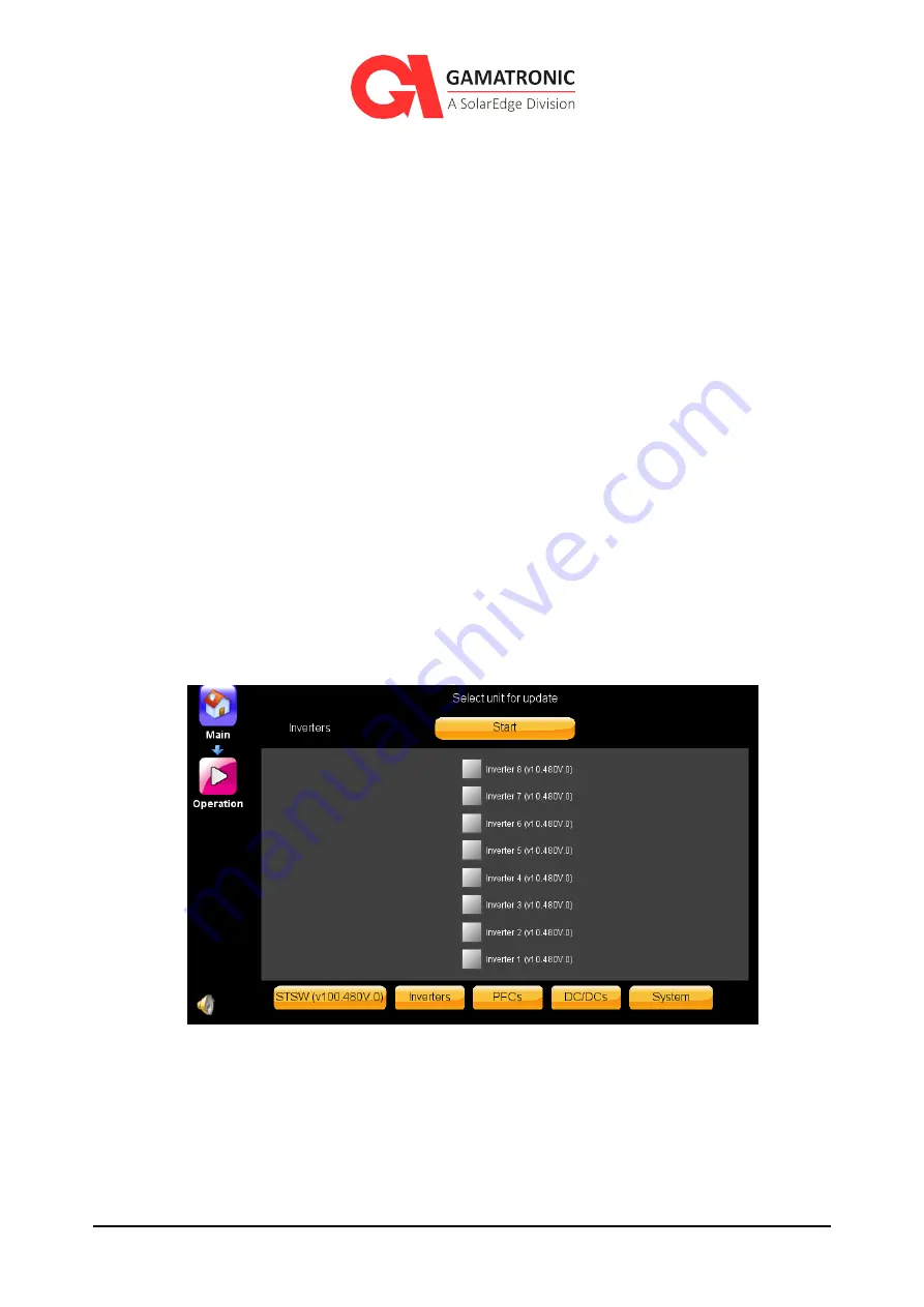
To update the inverters only: 

Select the Inverter(s) you would like to update 

Note that they are positioned in the same numbering layout as their physical position in the rack.  


Figure 150: Inverter update screen  

Press start to begin the firmware upgrade process.  

If you would like to update PFCs only: 

Select the PFC(s) you would like to update 

Summary of Contents for Gamatronic B240US

Page 1: ...GAMATRONIC THREE PHASE MODULAR UPS for the 480V grid B240US USER GUIDE Revision 4 0 Doc 2MUM B240U This user guide is for products B240US...

Page 2: ......

Page 3: ...UPS for 480 Vac Grid User Guide doc rel 4 0 1 Remember to register your product at http www gamatronic com product warranty in order to activate your warranty...

Page 4: ...AL BYPASS MODE 24 5 MANUAL EMERGENCY POWER OFF EPO 25 5 1 EPO INDICATION 25 5 2 BATTERY TRIP COIL DRY CONTACT 25 5 3 RESTARTING THE UPS AFTER EPO 26 6 UPS LCD USER INTERFACE 27 6 1 SYSTEM MENU LCD HOM...

Page 5: ...1 6 3 Set last maintenance date 51 8 2 1 6 4 System snapshot 51 8 2 1 6 5 Start logging 51 8 2 2 Setup MODULES 51 8 2 2 1 POWER MODULE AC INPUT VOLTAGE CALIBRATION 53 8 2 2 2 POWER MODULE AC OUTPUT VO...

Page 6: ...W System type 105 8 2 6 Setup ALARMS 106 8 2 6 1 Setup Alarms SET ALARM PRIORITIES 107 8 2 6 2 Setup Alarms ALARM LIMITS 107 8 2 6 2 1 Setup Alarms Alarm Limits dc VOLTAGE LIMITS 109 8 2 6 2 2 Setup A...

Page 7: ...N MENU 141 8 3 1 Operation Turn On Off SYSTEM ON OFF 142 8 3 1 1 Operation Turn on off SYSTEM ON 142 8 3 1 2 Operation Switch on off SYSTEM OFF 143 8 3 2 Operation Turn On Off MODULES ON OFF 144 8 3 2...

Page 8: ...s option 37 Figure 20 Operation Transfer load to Inverter option 37 Figure 21 Operation Battery Test option 38 Figure 22 Operation ECO Mode on option 38 Figure 23 Operation ECO Mode off option 38 Figu...

Page 9: ...ry Test Fault Voltage 85 Figure 65 Rectifier voltage at Battery Test 86 Figure 66 Automatic Battery Test Period 86 Figure 67 Next Battery Test Start Time 87 Figure 68 Setup Battery Battery Current 88...

Page 10: ...ent screen 123 Figure 107 Alarms button on email recipient screen 124 Figure 108 Alarm selection screen for email recipient 124 Figure 109 Setup Time menu options 125 Figure 110 Setup Time options 126...

Page 11: ...1 Figure 149 USB port locations 161 Figure 150 Inverter update screen 162 Figure 151 PFC update screen 163 Figure 152 DC DC update screen 163 Figure 153 System off warning 164 Figure 154 Calibration r...

Page 12: ...Figure 2 19 Table 2 Key to Figure 4 28 Table 3 Description of email parameters 122 Table 4 Alarms that can trigger output dry contacts 135 Table 5 Key to Figure 159 the Status screen 168 Table 6 Log m...

Page 13: ...ystem in any particular environment Operation and control of the UPS is accomplished through a touch sensitive LCD display screen In this manual when explaining how to navigate the control software vi...

Page 14: ...e for recommended clearances The UPS must be well grounded to the building s grounding system with a conductor that has a current carrying capacity that matches the rating of the UPS Battery installat...

Page 15: ...dc input output and battery circuit breakers and open all protective battery fuses for positive and negative poles as well as for mid points Verify 0v across all UPS terminals WARNING RISK OF LETHAL...

Page 16: ...portation Do not connect or disconnect any ac or dc cables to the battery cabinet or UPS unless ALL the battery circuit and ac circuit breakers are turned OFF Verify 0v across all UPS terminals Do not...

Page 17: ...e source Disconnection of all ac sources and dc sources is required to de energize this unit before servicing WARNING RISK OF LETHAL ELECTRIC SHOCK Do not touch uninsulated battery terminals WARNING R...

Page 18: ...lectrical efficiency of up to 96 98 in backup mode and up to 99 in ECO Mode This equipment has been tested and found to comply with the limits for a Class B digital device pursuant to part 15 of the F...

Page 19: ...city of 240kVA The UPS includes from one to eight modular lightweight hot swappable ac power modules each supplying 30 kVA kW and 1 to 4 modular lightweight hot swappable dc dc modules each supplying...

Page 20: ...UPS for 480 Vac Grid User Guide doc rel 4 0 18 Figure 1 B240 Model Front View...

Page 21: ...re 3 Connection Terminals Rear View Table 1 Key to Figure 2 ITEM DESCRIPTION A Protective earth ground bus bar B Midpoint terminal C AC RECTIFIER INPUT terminals L1 L2 L3 D AC BYPASS INPUT terminals L...

Page 22: ...s for data transfer and operation The UPS can operate without the System Controller but with reduced functionality The System Controller includes the LCD control panel used to monitor and operate the...

Page 23: ...s unable to supply sufficient power to the load for example in the event of an overload or an Inverter failure The Static Switch transfers high currents at very high speed a typical transfer time is l...

Page 24: ...of standard lead acid batteries If you plan to use lithium ion batteries you must supply your own BMS Battery Management System and you must follow Gamatronic special instructions for lithium ion bat...

Page 25: ...to receive power from the inverters but the dc input to the Inverter is taken from batteries via the dc converter modules instead of from the rectifier Battery mode is used whenever the grid power is...

Page 26: ...y isolate the UPS For additional information about configuring your site for external bypass mode refer to the instructions in the Installation Guide There may be occasions when your UPS service engin...

Page 27: ...t can be used to trigger an external circuit if desired such as a lamp or an audible alarm The LCD displays a shutdown by EPO and provides a visual and audible indication 5 2 Battery trip coil dry con...

Page 28: ...Switch OFF the following circuit breakers Ac input Bypass input Battery 3 Wait 1 minute 4 Switch on the ac input and bypass input circuit breakers 5 Switch ON the battery circuit breaker 6 Switch ON t...

Page 29: ...trol over the UPS and its operating parameters This chapter describes the most important and frequently used functions 6 1 System Menu LCD home screen The System Menu is the user s starting point for...

Page 30: ...active critical alarms i e error status indicating the most serious status a is displayed When there are one or more active warning status alarms and no error status alarms a is displayed When there...

Page 31: ...screen represented by that icon 6 2 System Menu Highlights This section provides a short overview of the System Menu options It also highlights the most frequently used options For detailed informatio...

Page 32: ...c rel 4 0 30 6 2 2 Status menu Selecting the Status option from the System Menu displays a diagram which summarizes the overall UPS state Figure 6 System Menu Status option The Status screen appears F...

Page 33: ...rent UPS component on the Status screen The Status screen is touch sensitive and interactive Pressing various icons on the screen reveal additional information about the selected component such as pre...

Page 34: ...vings time goes into effect and the accumulated operational time Figure 9 Setup Time option System date time must be accurate in order to enable technician level access and ensure accuracy of system t...

Page 35: ...iew various system parameters as defined by the factory or by your system technician Figure 11 System Menu Profile option Parameters for the overall system and for the battery Static Switch alarms and...

Page 36: ...User Guide doc rel 4 0 34 Figure 12 System Menu Log option Events listed include system power up and power down and the start and end of all alarm conditions For detailed information about Log options...

Page 37: ...UPS System off 3 Turn off power modules 4 Turn on power modules 5 Turn on dc module 6 Turn off dc module 7 Transfer the load to bypass 8 Transfer the load to Inverter 9 Test battery 10 ECO Mode For c...

Page 38: ...ation Turn off UPS option 6 3 3 Turn off power modules Figure 15 Operation Turn off power modules option This function can be used to just shut down the Inverter or completely shut down the power modu...

Page 39: ...17 Operation Turn on dc modules option 6 3 6 Turn off dc modules Figure 18 Operation Turn off dc modules option 6 3 7 Transfer load to bypass Figure 19 Operation Transfer load to bypass option 6 3 8...

Page 40: ...rid User Guide doc rel 4 0 38 6 3 9 Battery Test Figure 21 Operation Battery Test option 6 3 10 Turn on ECO Mode Figure 22 Operation ECO Mode on option 6 3 11 Turn off ECO Mode Figure 23 Operation ECO...

Page 41: ...occurred for any of the following reasons Due to battery exhaustion following an extended power outage Due to a manual shutdown performed by a technician prior to performing UPS maintenance Figure 24...

Page 42: ...ers and the message on the Status screen changes to UPS ON Normal mode 3 If instead of the expected message on the Status screen being UPS ON Normal mode the message remains UPS ON Bypass mode navigat...

Page 43: ...output To perform a total UPS shutdown with no ac output 1 Switch OFF the load device s 2 From the System Menu select Operation Turn ON OFF System OFF The System Menu screen appears Figure 25 UPS is...

Page 44: ...gure 26 LCD control panel displays the System Menu The user navigates the system by lightly pressing different system icons The current navigation path i e breadcrumb appears in the upper left hand co...

Page 45: ...n battery mode In the example shown above Figure 27 the user began navigation on the System Menu screen then chose Setup and finally chose Time The menus of the UPS are logically organized by function...

Page 46: ...em mode The icon signifies a Gamatronic password key is required After the key is used the function is enabled for the UPS If you do not have the appropriate Gamatronic key the key can be obtained thr...

Page 47: ...regarding the following parameters Nominal input and output values of the UPS Total number of modules and how many of them are redundant Output power capacity Multisystem ECO Mode or Self loading mode...

Page 48: ...NOMINAL SETTINGS Nominal system output voltage You can modify the nominal output voltage to any of the values listed on the screen but first you must turn off the UPS by means of the ON OFF button on...

Page 49: ...n the bypass frequency passes these boundaries the Inverter frequency ceases to be determined by the bypass frequency and comes under the control of the UPS s internal clock according to the nominal f...

Page 50: ...roperty of any particular module Redundancy is simply the presence of one or more modules in excess of the number of modules required to meet the maximum load As an example let s say We have a UPS sys...

Page 51: ...DESCRIPTION Enabled Make a checkmark here enable the ECO Mode function on the UPS Analyse grid Checkmark this field if you want the UPS software to decide the reliability of the mains voltage Custom...

Page 52: ...escends to the predefined level at which the UPS will turn itself off In this screen you also specify if the UPS should automatically turn itself back on when the ac mains power returns following a pr...

Page 53: ...vailable only to a technician to define new system alarms 8 2 1 6 3 Set last maintenance date The technician uses this function to record the date of the most recent preventive maintenance session 8 2...

Page 54: ...vider The following sections are for technician use only and should only be performed by trained professionals familiar with the system You should disable Auto Correction before making any changes cov...

Page 55: ...orrection is enabled by default This is the recommended setting for most situations After performing any calibrations or adjustments the Auto Correction feature should be re enabled for optimal system...

Page 56: ...OUTPUT VOLTAGE CALIBRATION Use this function if it becomes necessary to recalibrate the voltage readings of any of the UPS s output phases Note that this does not refer to the output reading of a par...

Page 57: ...ltage Calibration 2 For each output phase use a voltmeter to measure between the phase to midpoint 3 Type the measured amount into this screen and select Confirm This completes ac output voltage calib...

Page 58: ...most module and work your way up Auto Correction is enabled by default This is the recommended setting for most situations After performing any calibrations or adjustments the Auto Correction feature...

Page 59: ...firm This completes module input current calibration 8 2 2 4 POWER MODULE OUTPUT CURRENT CALIBRATION Use this function if it becomes necessary to recalibrate the current ampere readings of one of the...

Page 60: ...not subject to fluctuation Calibration is best performed when the system is under relatively high load 70 Auto Correction is enabled by default This is the recommended setting for most situations Aft...

Page 61: ...ted by a change in color of the numbers from white to orange are sent to the module For your reference the current UPS measured values are displayed on the right side of the screen 4 Switch OFF the mo...

Page 62: ...slightly Calibration of the dc voltage should be performed only under conditions where the UPS s input and output currents and voltages are stable and not subject to fluctuation Dc voltage calibratio...

Page 63: ...4 Open the rear fuse cover to expose the positive negative and mid point bus bars 5 Navigate to Setup Modules DC voltage calibration 6 The dc Voltage Calibration screen appears 7 Measure the voltage b...

Page 64: ...s 3 through 11 until all modules have been calibrated 8 2 2 6 AC OUTPUT VOLTAGE ADJUSTMENT Use this function to modify the voltages of the individual output phases of a specific power module The phase...

Page 65: ...er performing any calibrations or adjustments the Auto Correction feature should be re enabled for optimal system performance To detect and correct any inaccuracy in an ac power module output voltage...

Page 66: ...80 Vac Grid User Guide doc rel 4 0 64 Figure 42 Output terminals 7 Navigate to Setup Modules Ac output voltage adjustment 8 The Output Voltage Adjustment screen appears Figure 43 AC Output Voltage Cal...

Page 67: ...ls You would expect the value to be around 277Vac 3 V 15 Compare your measured value to the nominal output voltage 16 Adjust line 2 up or down accordingly to acquire the desired output voltage 17 Pres...

Page 68: ...performance The UPS s readings are calibrated before the UPS leaves the factory but over time or due to environmental factors the UPS s dc measurements may drift slightly Figure 44 DC Bus voltage Cal...

Page 69: ...all required safety precautions measure the voltage between the negative dc terminal and the midpoint terminal 5 Compare your measured value to the number to the right of the screen Figure 41 which is...

Page 70: ...st the rectifier dc voltage all other modules must be completely shut down and disconnect them from the system rack To disconnect the other modules from the system rack disconnect the PFC and inverter...

Page 71: ...y but on the same screen and can be increased or decreased separately To correct inaccuracy in UPS dc bus voltage 1 Isolate and turn off all ac and dc power to the UPS 2 Remove the back fuse cover 3 T...

Page 72: ...up or down accordingly to acquire the desired negative dc voltage 12 Press confirm 13 Wait 5 seconds and verify that the negative dc voltage has changed accordingly 14 Measure voltage between the posi...

Page 73: ...r module is set by default Technicians should Only perform this in case of a module calibration reset 8 2 2 10 AUTO CORRRECTION When the average output voltage of the Ac modules is above or below what...

Page 74: ...stments the Auto Correction feature should be re enabled for optimal system performance 8 2 2 11 POWER WALK IN At system startup this parameter give you control of the time it takes to bring the syste...

Page 75: ...onversion modules Most of these parameters are for calibrating the UPS s readings of the several dc voltages related to the conversion function Remember that the dc to dc conversion modules boost the...

Page 76: ...The UPS s readings are calibrated before the UPS leaves the factory but over time or due to environmental factors the UPS s dc measurements may drift slightly Keep in mind that in this screen Figure 5...

Page 77: ...any inaccuracy in the UPS s display of the battery voltage 1 Measure the actual battery voltage with a calibrated voltmeter There are labeled battery dc bus bars inside the UPS Carefully observing al...

Page 78: ...he value you measured differs from the UPS s measured value enter your measured value into the field labeled Battery positive dc voltage Figure 53 6 Press Confirm The corrected positive voltage measur...

Page 79: ...o load during the dc output voltage calibration A password may be required to perform this function To calibrate the UPS s display of the dc voltage 1 Turn off all dc dc blocks except for one Main Ope...

Page 80: ...alue differs from the UPS s measured value enter your measured value into the field labeled Negative dc voltage 4 Next measure the voltage between the positive dc bus and the midpoint bus bar If your...

Page 81: ...will insure maximum current to the dc converter module To calibrate the UPS s display of the charger current 1 With the UPS in normal mode turn off the ac input Main Operation Turn ON OFF Modules Off...

Page 82: ...ger current calibration screen 8 2 3 4 Dc to dc voltage adjustments This function enables you to adjust the voltages out of each individual dc dc block Adjustments are made to each dc dc block separat...

Page 83: ...ac input the input circuit breakers are in the OFF position 8 2 3 6 Adjusting the battery voltage the buck voltage The fields labeled Battery positive dc and Battery negative dc effect the voltage bet...

Page 84: ...tery voltages should be made only when the battery is fully charged 8 2 3 7 Serial Numbers Use this function to record the serial numbers of the UPS s modules Figure 60 Serial Numbers The serial numbe...

Page 85: ...rofessionals familiar with the system Setup BATTERY functions provide control over several battery parameters Figure 61 Setup Battery menu options The UPS supports the use of standard lead acid batter...

Page 86: ...User Guide doc rel 4 0 84 Figure 62 Setup Battery menu hierarchy 8 2 4 1 Setup Battery BATTERY TEST PARAMETERS The parameters in this section relate to the battery test function Figure 63 Battery Batt...

Page 87: ...tteries are unable to hold the minimum charge the battery test will fail due to one of the batteries having a lower voltage than 11 75 V dc Figure 64 Battery Test Fault Voltage Battery test failure wi...

Page 88: ...at Battery Test Do not change the default setting 8 2 4 1 3 Automatic battery test interval The UPS conducts a periodic battery test automatically according to the time interval specified here Figure...

Page 89: ...charged from the mains for eight consecutive hours since its last significant discharge the test is postponed until the battery is fully charged 8 2 4 1 4 Maximum duration of battery test Set the max...

Page 90: ...e or disable external battery current sensors Figure 69 Enable Disable Current Sensors 8 2 4 2 2 Calibrate battery current This function is used to calibrate battery current reading for any of the bat...

Page 91: ...ect the UPS to its batteries and to a load and operate the UPS in battery mode Figure 70 Calibrate Current 4 Measure the actual battery current and correct the controller reading if necessary using th...

Page 92: ...UPS without a load and with batteries disconnected 2 Perform the Set dc current offset function only if the measured current is not zero 3 Connect the UPS to its batteries and to a load and operate th...

Page 93: ...There are two options Set maximum battery current to 0 1 x battery capacity Set maximum battery current to 0 2 x battery capacity 8 2 4 2 5 Minimum dc voltage at current limit Use this function to set...

Page 94: ...ended for most situations 8 2 4 3 Setup Battery End of Backup voltage limit During a mains power blackout the batteries provide power to the UPS s Inverter In the process the battery voltage continual...

Page 95: ...charge which shortens battery life The voltage limit is expressed in terms of volts per battery block The normal voltage of a battery block is between 12 and 13 5 volts The end of backup battery volta...

Page 96: ...your battery capacity look at one of the battery cells The Ah rating of a battery cell is usually indicated on the outside of the cell This same number is your battery capacity 8 2 4 5 Setup Battery...

Page 97: ...mpensation See Figure 76 1 temperature sensor installed If you have one temperature sensor installed select this option 2 temperature sensors installed If you have two temperature sensors installed se...

Page 98: ...voltage at compensation slider 5 Adjust the highest charging voltage to be used when battery temperature compensation is enabled by changing the High limit of battery voltage at compensation slider T...

Page 99: ...urces If this drain continues for a long period of time it can result in a deep discharge of the battery which shortens battery life To protect the battery from deep discharge the LVD function Low Vol...

Page 100: ...VD screen Any one of the eight output dry contacts can be used to signal that the LVD countdown is in progress For the wiring set up for the LVD function see the UPS Installation Guide under the headi...

Page 101: ...2 5 Setup STATIC SWITCH For complete instructions contact your service provider The following sections are for technician use only and should only be performed by trained professionals familiar with...

Page 102: ...id User Guide doc rel 4 0 100 Figure 81 Setup Static Switch options 8 2 5 1 Setup STSW CALIBRATE BYPASS VOLTAGE For calibration of the bypass voltage reading by phase Figure 82 Static Switch Bypass Vo...

Page 103: ...ng 8 2 5 2 Setup STSW CALIBRATE OUTPUT VOLTAGE For calibration of the ac output voltage reading by phase Figure 83 Static Switch Output Voltage This voltage is a phase to ground reading 8 2 5 3 Setup...

Page 104: ...ent calibration should be performed only if necessary not casually Static Switch output current calibration should be performed only under conditions where the system input and output currents are sta...

Page 105: ...to bypass mode this function determines whether the controller will check the quality of the bypass voltage or not before moving to bypass Select Forced if you want the UPS to move to bypass regardle...

Page 106: ...ppx 236 318 V or narrow appx 250 305 V 8 2 5 5 Setup STSW OVERLOAD HYSTERISIS This option sets the load level at which the load returns to the Inverter after being transferred to bypass due to an over...

Page 107: ...isable Analysis Event This log information can be used by a technician when troubleshooting 8 2 5 7 Setup STSW System type Informs the Static Switch of the system type in which it is installed in term...

Page 108: ...type should not be changed 8 2 6 Setup ALARMS For complete instructions contact your service provider The following sections are for technician use only and should only be performed by trained profes...

Page 109: ...in your site an alarm condition is more or less important that the default value assigned to the alarm This function allows you to override the default value for a given alarm You can scroll through...

Page 110: ...UPS for 480 Vac Grid User Guide doc rel 4 0 108 Figure 91 Alarms Alarm Limits...

Page 111: ...e levels at which the dc VOLTAGE HIGH and dc VOLTAGE LOW will be activated Figure 92 Alarms limit dc voltage limit configuration These parameters should not be changed 8 2 6 2 2 Setup Alarms Alarm Lim...

Page 112: ...and off many times rapidly The hysteresis value is the number of volts that a measurement must change before an alarm senses that the measurement has changed So in the example above if you set a hyst...

Page 113: ...ms Alarm Limits TEMPERATURE LIMITS This function lets you set the temperature in C at which the high temperature alarm and low temperature alarm are generated The temperature is read from an optional...

Page 114: ...CONFIGURATION This function allows you to adjust each of the system alarm warning sensitivity levels All system alarms by default are added to the log These parameters should not be changed If you wan...

Page 115: ...ckbox the selected alarm will be ignored all together If you select the For log only checkbox the selected alarm will only be added to the log file You can change the default alarm priority of a speci...

Page 116: ...patible with Windows Windows NT and Linux networks Use of the built in web interface on Windows requires the Microsoft Internet Explorer browser version 7 or higher An SNMP agent and the associated MI...

Page 117: ...2 7 2 Network configuration options 8 2 7 2 1 Network configuration OBTAIN IP ADDRESS AUTOMATICALLY This is the right choice if your computer network supports dynamic assignment of IP addresses DHCP...

Page 118: ...options 2 Select Add new community The NEW SNMP community screen appears Figure 99 Creating a new community 3 Type in the desired community name in the Community name text input field and select the a...

Page 119: ...lete at the bottom of the screen The community is deleted 8 2 7 3 2 SNMP configuration ACCEPT SNMP PACKETS FROM THESE HOSTS Selecting this check box allows SNMP packets to be accepted from any host Yo...

Page 120: ...gement Information Base standard For additional information refer to Section 8 2 7 3 1 8 2 7 4 Optional feature Setup Connectivity Serial Communication Serial communication is an optional feature avai...

Page 121: ...ually exclusive In either case with regards to Modbus the UPS is a slave device to the Modbus master located elsewhere on the Modbus communication network The UPS will respond to queries from the Modb...

Page 122: ...S s physical connection for serial Modbus is a 4 pin connector P5 located in connector group 2 and labeled RS485 3 Select Confirm For a table of information relating to Modbus Queries refer to Table 7...

Page 123: ...dition started or Off alarm condition ended Figure 103 Example of email message body You must configure several parameters in order to use the optional email alarm notification Optional To use the ema...

Page 124: ...sending email address You are prompted for the email address and its password Enable TLS Enable the TLS encryption protocol for the outgoing emails SENDER EMAIL ADDRESS This address will appear in th...

Page 125: ...ents screen 2 Select Add new recipient 3 The New email recipient screen appears Figure 106 New email recipient screen 4 Type the recipient s email address in the Email text input field 5 Optional Type...

Page 126: ...wing screen appears Figure 108 Alarm selection screen for email recipient In this screen you indicate the alarms that you want to be included in the emails to the current recipient Buttons appearing a...

Page 127: ...is especially useful when there is more than one UPS connected to the network If you give each UPS a unique name the network manager will be able to distinguish between them This can be helpful in the...

Page 128: ...date and time Enter the year month day hour minute and second 8 2 8 2 Setup Time ADJUST DATE TIME To set date time 1 Modify any or all the date time fields as required year month day hours minutes an...

Page 129: ...e Time Synchronization This will only work when connected to a network Figure 112 Setup Time Time Synchronization 8 2 8 5 Setup Time SET LAST MAINTENANCE DATE This function allows you to keep a record...

Page 130: ...ve text to be associated with the unit Figure 113 Setup Assign Site ID When the UPS is connected to a computer network this information can be seen by someone who is monitoring the UPSs via an SNMP pr...

Page 131: ...Guide doc rel 4 0 Figure 114 Assigning a site ID For the authorization level of User the descriptors are shown in Figure 114 Click on a field to display the virtual keyboard which you can use to ente...

Page 132: ...bles the user to manage the UPS s input and output dry contacts Figure 115 Setup Dry Contacts menu A password may be required to use functions available in this menu If you do not have the appropriate...

Page 133: ...irs of input dry contacts on the UPS and that pair of input dry contacts can then be programmed to generate an alarm condition when the battery circuit breaker is opened 8 2 10 1 1 Location of the inp...

Page 134: ...ry contacts You can see these alarms in the Setup Alarms function They are named Auxiliary 1 fault through Auxiliary 5 fault These names can be modified by the user Provided that the input dry contact...

Page 135: ...f the output dry contact will change Any number of output dry contacts can be linked to a single alarm condition Each output dry contact can be linked to any number of alarm conditions The output dry...

Page 136: ...e of fault 23 Overload current 24 Battery test in progress 25 UPS shutdown by Off button LCD panel 26 UPS shutdown by remote user command 27 UPS shutdown by end of battery backup 28 UPS shutdown by ov...

Page 137: ...on low voltage 56 Output contactor fault 57 System is locked by multiple overloads 58 Load is now running on converter 59 Maintenance bypass 60 Failed To Return On ECO 61 Failed testing transfer to in...

Page 138: ...the output dry contact screen see Figure 119 Pressing the Test button changes the state of the output dry contact to its non Normal condition for about five seconds 8 2 10 3 Generator Mode setup This...

Page 139: ...the current UPS settings and restore them later Figure 121 Setup Save Restore options This would enable you to experiment with new settings and then easily return to the previous settings There is als...

Page 140: ...g this function does not have any effect on what is saved by the SAVE SETTINGS function above The Restore Factory Settings function is only displayed in Technician mode Be aware that using the Restore...

Page 141: ...rel 4 0 8 2 12 Setup AUTHORIZATION Figure 122 Setup Authorization System time date must be correct in order to enable Technician level access This function allows you to switch to a different user lev...

Page 142: ...y is hidden from User level 8 2 12 2 Setup Authorization ENABLE DISABLE REMOTE CONTROL Use this function to enable disable remote system access This functionality enables restricts UPS access from a r...

Page 143: ...141 UPS for 480 Vac Grid User Guide doc rel 4 0 8 3 OPERATION menu Figure 125 System Menu Operation menu hierarchy tree Figure 126 Operation Menu...

Page 144: ...UPS on off 8 3 1 1 Operation Turn on off SYSTEM ON This section explains how to turn the UPS on following normal shutdown To turn the UPS on 1 Verify that the input and battery circuit breakers are i...

Page 145: ...wn above 3 Select System On The This action will turn all the modules on confirm dialog appears Figure 128 Confirm dialog Turn all modules on 4 Select OK The UPS takes about two minutes to perform a s...

Page 146: ...ULES ON OFF 8 3 2 1 Operation Turn on off MODULES OFF Use this function to turn power modules OFF You can selectively turn off individual modules or all of them at once And you can choose what level o...

Page 147: ...The selected power modules are highlighted in blue 3 If you select the Inverter Off you be will be disconnecting those specific power modules output You will be returned to the previous screen 4 If yo...

Page 148: ...ower modules you want to turn on The selected power modules are highlighted in blue 3 Click Confirm The power modules go through a series of activation processes This can take up to two minutes The po...

Page 149: ...r The load is unaffected Figure 132 Switch On Off Controller Restart The controller is restarted 8 3 3 2 Operation Turn on off CONTROLLER SHUTDOWN Use this function to shut down the controller The loa...

Page 150: ...Figure 133 Switch On Off Controller Shutdown To reset the System Controller there is a recessed Reset button available on the back of the controller panel adjacent to the USB ports Figure 134 Control...

Page 151: ...s buttons will be grayed out if the bypass and the inverter are not synchronized Transfers the load from the Bypass voltage to the Inverter voltage Figure 135 Operation Transfer load to Inverter The T...

Page 152: ...tions in the local ac power When the load is on the Inverter battery backup is always ready to ensure a continuous power supply even in the event of a local ac power failure Transferring the load to b...

Page 153: ...t Operation Transfer load Transfer load to bypass The Transfer load to Bypass confirm dialog appears Figure 137 Transfer load to bypass 2 Select OK The load is transferred from Inverter voltage to byp...

Page 154: ...o ECO mode In ECO Mode the UPS s normal state is bypass mode The mains power bypasses the UPS s rectifier and Inverter to feed the load directly When the UPS in ECO Mode detects an irregularity in the...

Page 155: ...some other anomaly The advantages and disadvantages of an ECO Mode UPS must be weighed against each other A UPS operating in ECO Mode can be effective in a situation where the critical load is not sup...

Page 156: ...it before returning the load to bypass The Define Timeouts parameter enables you to change the numeric weight of the Custom Reliability buttons in the ECO Mode screen 4 Select Confirm You have now ena...

Page 157: ...uses this information to determine which ECO Mode Custom Reliability setting is most appropriate for your environment 5 Select Confirm You have activated ECO mode with Analyze grid in the system If y...

Page 158: ...e the time to transfer back to ECO Mode from Inverter after an anomaly in the grid 6 Customize the settings in the Define Timeouts screen according to the selected customized reliability setting you c...

Page 159: ...ave successfully enabled analyze grid as well as customized reliability timeout settings The next step is to transfer the UPS to ECO Mode To transfer the UPS to ECO Mode 1 From the System Menu select...

Page 160: ...m ECO Mode is turned on 3 Navigate to the Status screen The Status screen appears Figure 144 UPS is on ECO Mode is turned on and Inverter is in standby state Notice the Status screen when the UPS ON a...

Page 161: ...Operation Firmware Update The firmware update function allows a service technician to update the various subsystems software Firmware updates should be performed only after consulting the service cent...

Page 162: ...system and subsystem selection screen appears Figure 147 Select unit for update 3 Select from one of the subsystems to upgrade exclusively If you intend on updating all of the subsystems you can do s...

Page 163: ...l 4 0 Figure 148 Insert USB screen The USB drive can be inserted into any of the three available USB slots located on the side of the system controller Figure 149 USB port locations 4 Insert the USB w...

Page 164: ...elect STSW see Figure 147 Press start to begin the firmware upgrade process Wait as the system upgrades the static switch with the relevant firmware To update the inverters only Select the Inverter s...

Page 165: ...s If you would like to update DC DC blocks only Select the DC DC block s you would like to update Note that they are positioned in the same numbering layout as their physical position in the rack Figu...

Page 166: ...ions back to the factory default settings and the effected subsystems may require recalibrating to fit the site requirements To perform a calibration reset 1 Navigate to Main Operation Calibration res...

Page 167: ...e same numbering layout as their physical position in the rack Figure 155 Inverter calibration reset screen Once you press on the inverter icon the inverter will revert to factory default settings To...

Page 168: ...efault settings To reset the calibrations of the DC DC blocks only Select the DC DC block s you would like to reset Note that they are positioned in the same numbering layout as their physical positio...

Page 169: ...4 STATUS menu The Status screen summarizes the UPS current state Figure 158 System Menu Status option To view the UPS Status 1 From the System Menu select Status The Status screen appears Figure 159 T...

Page 170: ...mponent at the point where the triangle is located Clicking on the component will provide more detailed information about the problem Clicking various parts of the Status screen diagram reveals additi...

Page 171: ...phic represents the Ac power modules Pressing this icon gives access to detailed readings of each UPS module s ac input ac output dc current status and nominal values 7 Modules alarm icon When present...

Page 172: ...the bypass input icon button displays more detailed readings for all output phases 12 Modules alarm icon When present indicates that there is an active alarm condition for one or more of the dc conver...

Page 173: ...a summary of the operating parameters of various parts of the system Figure 160 System Menu Profile options 8 5 1 Profile SYSTEM Figure 161 Profile System Lists the current values for a number of bas...

Page 174: ...f modules Last maintenance date Number of DCDC blocks Model type Number of modules for redundancy Multi system mode More information about these parameters is available in Section 8 2 1 8 5 2 Profile...

Page 175: ...ve inactive Automatic battery test period in weeks Temperature compensation status active inactive Test duration limit Temperature compensation factor mV C Current sensor status active inactive Limit...

Page 176: ...ound in Section 8 2 5 8 5 4 Profile ALARMS Lists current parameter values mostly alarm limit values for alarms including Dc voltage high limit Dc voltage low limit Ac voltage high limit Ac voltage low...

Page 177: ...0 8 5 5 Profile IDENTIFICATION Figure 164 Profile Identification Lists several identifiers Manufacturer Location Model name Attached devices Software version System serial number Identification Contac...

Page 178: ...oldest messages so that the log file always contains the latest log events Every log message has a severity level assigned to it There are four different severity levels as described in Table 6 Table...

Page 179: ...ing The full log can be exported to a USB drive for analysis Scroll through the log messages by sliding your finger up or down the touch sensitive screen or use the UP and Down arrow keys To display d...

Page 180: ...he Log Event screen displays detailed readings for the selected system component as was recorded at the time of the log entry You can navigate to the detailed readings for the previous or the next log...

Page 181: ...een Alarm button can be seen Figure 168 Alarms display from the Log detail screen Selecting this button displays a list of all alarms that were active at the time the log record was viewed This can be...

Page 182: ...u are using the remote access feature which enables monitoring and control of the UPS from a remote computer over an intranet or the Internet Figure 169 System Menu Connectivity option Figure 170 Conn...

Page 183: ...enu Time option Figure 172 Time function on the System Menu 8 9 LANGUAGE menu From the System Menu the Language function gives you the ability to choose the language in which the display screen option...

Page 184: ...shorten the batteries lifespan The UPS and its batteries both require periodic preventive maintenance inspections At the least these inspections should include a visual inspection of the UPS and its...

Page 185: ...ircuit breaker on the battery cabinet must be switched OFF The UPS s battery circuit breaker if any must also be switched OFF WARNING RISK OF LETHAL ELECTRIC SHOCK The battery cabinet contains batteri...

Page 186: ...proper maintenance under certain conditions excessive amounts of hydrogen may be emitted from some batteries in the string when charging takes place This can result in a dangerous accumulation of hyd...

Page 187: ...able backup time 6 4x0006 Estimated Charge 0 100 Mathematical estimation of battery charge in percent 7 4x0007 Battery Voltage 10 Vdc Divide the value by 10 for real measurement 485 10 48 5 Vdc 8 4x00...

Page 188: ...e 2 10 A Divide the value by 10 for real measurement 21 10 2 1 A 34 4x0034 Output Load Line 2 Some units might show values over 100 in case of overload 35 4x0035 Output Voltage Line 3 10 Vac Divide th...

Page 189: ...g modules 205 4x0205 Amount of Battery Cabinets As defined by controller settings 206 4x0206 Multisystem Mode Parallel Operation 0 Stand alone 1 Multisystem As defined by controller settings 207 4x020...

Page 190: ...the value by 10 for real measurement 21 10 2 1 A 222 4x0222 Inverter Power Line 1 10 kW Divide the value by 10 for real measurement 453 10 45 3 KW 223 4x0223 Inverter Apparent Power Line 1 10 kVA Div...

Page 191: ...Hz 244 4x0244 Charger Power factor Line 2 0 to 100 Divide the value by 100 for real measurement 87 100 0 87 PF 245 4x0245 Charger Load level Line 2 246 4x0246 Charger Voltage Line 3 10 V Divide the v...

Page 192: ...ivide the value by 10 for real measurement 453 10 45 3 KW 269 4x0269 Output Apparent Power Line 3 10 kVA Divide the value by 10 for real measurement 769 10 76 9 KVA 270 4x0270 Output Power Factor Line...

Page 193: ...0 Alarm off 1 Alarm on 308 4x0308 Module 7 Alarm 0 Alarm off 1 Alarm on 309 4x0309 Module 8 Alarm 0 Alarm off 1 Alarm on 310 4x0310 Module 9 Alarm 0 Alarm off 1 Alarm on 311 4x0311 Module 10 Alarm 0...

Page 194: ...off 1 Alarm on 336 4x0336 No Output Current On Modules 0 Alarm off 1 Alarm on 337 4x0337 Overload 0 Alarm off 1 Alarm on 338 4x0338 Battery Test In Progress 0 Alarm off 1 Alarm on 339 4x0339 Auxiliary...

Page 195: ...1 Alarm on Only for Mega modular UPS in 20 module configuration 359 4x0359 Module Switching Adaptor Is Not Switching 0 Alarm off 1 Alarm on Only for Mega modular UPS in 20 module configuration 360 4x0...

Page 196: ...4 Register Variable name GET Values Remarks 367 4x0367 Controller Thread Limit Reached 0 Alarm off 1 Alarm on 368 4x0368 Controller Memory Limit Reached 0 Alarm off 1 Alarm on 369 4x0369 Controller Di...

Page 197: ...l rights reserved SOLAREDGE the SolarEdge logo OPTIMIZED BY SOLAREDGE are trademarks or registered trademarks of SolarEdge Technologies Inc All other trademarks mentioned herein are trademarks of thei...

Page 198: ...UPS for 480 Vac Grid User Guide doc rel 4 0 196 CHANGE LOG Doc release 1 April 2019 Original release Doc release 2 December 2019 Full document update Doc release 3 April 2020 Partial document update...

Reviews: