


WATTrouter Mx - user manual
How to fit and setup the device
Page 64 from 82
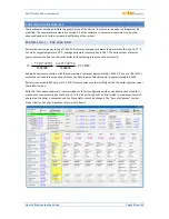
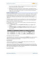
By sending this HTTP request you will obtain the current measured/status data from the controller (actual
measured powers in individual phases and power/energy values for connected loads). Structure of
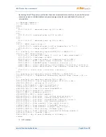
returned data:
<!--Response headers-->
<!--one empty line-->
<meas>
<I1>
<P>-2.20</P><!-- measured power by IL1 in kW-->
</I1>
<I2>
<P>1.50</P><!-- measured power by IL2 in kW-->
</I2>
<I3>
<P>-1.10</P><!-- measured power by IL3 in kW-->
</I3>
<I4><!-- ANDI1 input status-->
<P>0.50</P><!--
measured power in kW or temperature in °C
-->
<E>1.60</E><!-- energy counted in kWh-->
</I4>
<!-- similarly for remaining inputs ANDI2(I5) to ANDI4(I7)-->
<O1><!-- SSR1 output status-->
<A>0</A><!-- assigned ANDI input (1 to 4) or 0 when unassigned-->
<P>1.00</P><!-- load power in kW-->
<E>3.00</E><!-- supplied energy to connected load in kWh-->
<HN>1</HN><!-- basic control mode: 0=inactive, 1=active-->
<HC>0</HC><!-- CombiWATT mode: 0=inactive, 1=active -->
<HE>0</HE><!-- output enforced by time schedule: 0=inactive, 1=active-->
<HR>0</HR><!-- output restricted by time schedule: 0=inactive, 1=active--
>
<T>0</T><!-- output test: 0=inactive, 1=active-->
</O1>
<!-- similarly for remaining outputs SSR2(O2) to WLS6(O14)-->
<DQ1>20.0</DQ1><!-- temperature measured by digital temp. sensor D/Q1 in
°C
-->
<!-- similarly for remaining sensors DQ2 to DQ4-->
<PPS>-1.80</PPS><!-- sum of measured powers L1+L2+L3 in kW-->
<VAC>230</VAC><!-- voltage at L1 in V-->
<DaR>1.1.2017</DaR><!-- date (controller)-->
<TiR>0:00:00</TiR><!-- time (controller)-->
<CW>7200</CW><!-- time to activate CombiWATT-->
<DC>12.0</DC><!--internal DC source-->
<FW>1.0</FW><!-- firmware version-->
<SN>46000001</SN><!-- serial number-->
<EL1>0</EL1><!-- 0=no fault, 1=L1 voltage missing error-->
<ELV>0</ELV><!-- 0=no fault, 1=Wrong voltage value L1-->
<ETS>0</ETS><!-- 0=no fault, 1=temperature sensor(s) error-->
<EDC>0</EDC><!-- 0=no fault, 1=DC source overload-->
<ILT>0</ILT><!-- 0=not present, 1=low tariff active-->
<ICW>0</ICW><!-- 0=not present, 1=CombiWATT active-->
<ITS>0</ITS><!-- 0=not present, 1=output test active-->
<IDST>0</IDST><!-- 0=not present, 1=summer time-->
<ISC>0</ISC><!-- 0=not inserted, 1=inserted SC-Gateway module-->
<SRT>6:00</SRT><!-- sunrise time-->
<DW>1</DW><!-- day of week (0=Monday to 6=Sunday)-->
</meas>
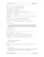
2.
GET /conf.xml