


WATTrouter Mx - user manual
How to fit and setup the device
Page 35 from 82
external single-phase meters, or 3 external current transformers. Another current sensing module can also be
used to measure the PV production itself in this case.
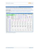
Energy offset - this field can be used to set initial values of measured energies. If the values of
measured energies do not match the display on the connected energy meter (for example), put the
value of the energy shown on the display into this column and reset impulse counters to zero by
marking the option "Reset energy".
Reset energy - used to reset energy counters to zero.
Number of impulses per one kWh – this column is used to set the number of impulses per one kWh,
when the ANDI input function is set to S0 pulse counter. Set the value according to the label or manual
of the connected energy meter, inverter or according to another compatible measuring instrument. It
is recommended to use highest possible amount of impulses per kWh to get better resolution for the
power fields in the “ANDI input status” group.
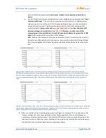
Input checking oscilloscope:
This graph is primarily used to check the correctness of ILx metering inputs settings and/or ANDI inputs settings
when their function is set to power measurement. However, it can also be used to check ANDI input
configuration for other selected functions. From the drop-down menu, select the input you want to check and
follow the chart.
The oscilloscope will always display the events at the analog inputs of the WATTrouter microprocessor, which
will vary according to the assigned input function:
a.
Power measurement - one whole period of measured current is displayed, the value for zero
measured power should be around 2000 digits. For more information about this view, see chapter
Setting up main function.
b.
S0 pulse counter - logic 1 (about 4000 digits) will be displayed for pulse delay or logic 0 (about 10
digits) for the active pulse from the meter.
c.
NTC, PT1000 - the analog value measured by the sensor or amplified by the built-in programmable
amplifier is displayed, which is further processed by the microprocessor for the temperature readout.
In case of connection of external current transformers, S0 pulse outputs or temperature sensors
to the ANDI multipurpose inputs, it is imperative to correctly configure their function or
otherwise even the ILx inputs may not work properly! You will see this as wrong diagram in the
input checking oscilloscope.
Digital temperature sensors:
Sensor type – select the type of connected digital sensors. All sensors must be of the same type.
Search for digital temperature sensors - starts searching for digital sensors connected to the DQ bus. If
all connected sensors do not appear after performing this function, make sure that the data bus
connection is correctly wired and that the shielding is also connected and working. Frequent errors in
communicating with sensors occur especially at longer distances and incorrect shielding. The feature is
password protected against unauthorized access.
Labels – used to assign a label for the relevant input. Label may contain a maximum of 16 characters
in ASCII encoding.
OUTPUT SETTINGS TAB
On this tab you may set basic parameters for outputs and setup the CombiWATT mode for outputs.