TaBLE OF CONTENTS
i
mportant
S
afety
i
nStructionS
. . . . . . . . . . . . . . . . . . . . . . . . . . . . . . . . . . . . . . . . . . . . . . . . . . . . . . . . . . . .
1
1.0 G
loSSary
of
S
ymbolS
. . . . . . . . . . . . . . . . . . . . . . . . . . . . . . . . . . . . . . . . . . . . . . . . . . . . . . . . . . . . . . .
3
2.0 i
ntroduction
and
S
yStem
d
eScription
. . . . . . . . . . . . . . . . . . . . . . . . . . . . . . . . . . . . . . . . . . . . . .
4
3.0 S
yStem
d
eScription
. . . . . . . . . . . . . . . . . . . . . . . . . . . . . . . . . . . . . . . . . . . . . . . . . . . . . . . . . . . . . . . . . .
5
3.1
Transient Voltage Surge Suppression (TVSS) and EMI/RFI Filters. . . . . . . . . . . . . . . . . . . . . . . . . .
5
3.2
Rectifier/Power Factor Correction (PFC) Circuit ...............................................
5
3.3
Inverter. . . . . . . . . . . . . . . . . . . . . . . . . . . . . . . . . . . . . . . . . . . . . . . . . . . . . . . . . . . . . . . . . . . . . . . . . . . . . . . . . . . . . . . . . . . . . .
5
3.4
Battery Charger....................................................................................
5
3.5
DC to DC Converter................................................................................
6
3.6
Battery...............................................................................................
6
3.7
Static Bypass.......................................................................................
6
4.0 m
ajor
c
omponentS
. . . . . . . . . . . . . . . . . . . . . . . . . . . . . . . . . . . . . . . . . . . . . . . . . . . . . . . . . . . . . . . . . .
7
4.1
Main Frame and Electronics. . . . . . . . . . . . . . . . . . . . . . . . . . . . . . . . . . . . . . . . . . . . . . . . . . . . . . . . . . . . . . . . . . . . . .
7
4.2
Internal Battery Pack..............................................................................
7
4.3
Input/Output Terminal Blocks and Optional Output Distribution...............................
8
5.0 w
hat
’
S
i
ncluded
. . . . . . . . . . . . . . . . . . . . . . . . . . . . . . . . . . . . . . . . . . . . . . . . . . . . . . . . . . . . . . . . . . . . .
9
6.0 i
nStallation
and
c
onfiGuration
. . . . . . . . . . . . . . . . . . . . . . . . . . . . . . . . . . . . . . . . . . . . . . . . . . . . .
10
6.1
Install the Main Cabinet...........................................................................
10
6.1.1 Tower UPS Installation....................................................................
10
6.1.2 Installing the Adjustable Rack-Mount Kit—Sold Separately...........................
11
6.2
External Battery Cabinet Installation.............................................................
13
6.3
Connect Input/Output Power.....................................................................
14
6.3.1 Distribution Module Electrical Connections.............................................
14
6.3.2 Input & Output Terminal Block Connections............................................
15
6.3.3 Add an Output Power Distribution Module—Optional.................................
16
6.4
Install the Internal Battery Pack..................................................................
17
7.0 i
nitial
S
tartup
and
e
lectrical
c
heckS
. . . . . . . . . . . . . . . . . . . . . . . . . . . . . . . . . . . . . . . . . . . .
18
7.1
Hardwire Input Connections......................................................................
18
7.2
Output Receptacle Distribution Options.........................................................
19
i
Summary of Contents for S4K6U10000
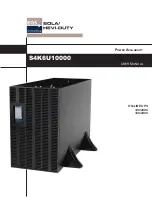
Page 1: ...S S4K6U10000 power availability On Line UPS 120 208V 120 240V USER MANUAL...
Page 2: ......
Page 46: ......
Page 47: ......

