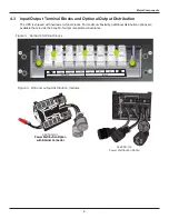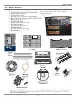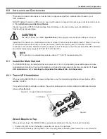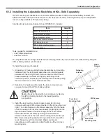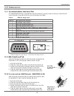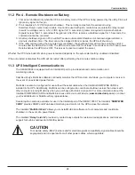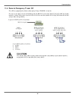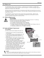
i
nstallation and Configuration
6.2 External Battery Cabinet Installation
Optional Sola/Hevi-Duty external battery cabinets maybe connected to the UPS to provide additional battery
runtime. External battery cabinets are designed to be placed on one side of the UPS or stacked beneath
the UPS.
The external battery cabinet frame and battery kits are shipped separately. This 4U cabinet arrives without
internal batteries to lighten the cabinet for easier installation. Once the cabinet has been placed in its final floor
or rack position, the internal batteries may be installed.
CaUTION
The external battery cabinet(s) are heavy (see
14.0 - Specifications
). External battery cabinets can
be used in rack-mount or tower configuration. Take proper precautions when lifting them.
CaUTION
Verify that the battery cabinet circuit breaker is in the OFF position. Do not energize the battery
cabinet at this time. When installation is complete, you will be instructed to turn on the circuit breaker.
When the external battery cabinet is received, it should be inspected for freight damage. Report damage to the
carrier and your local distributor or Sola/Hevi-Duty representative.
To install an external battery cabinet:
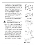
1. For slide rail installations, first remove the top bezel. Optional rack-mount handles are shipped with the
external battery cabinet and maybe installed now. (Securing hardware and slide rails are sold separately.
Please contact your local distributor or Sola/Hevi-Duty representative for these additional options and any
assistance needed.)
2. Fasten the slides into position with the screws according to the instructions included with the slide rails.
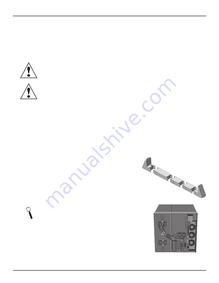
3. Use the enclosed support bases for the tower option to prevent the assembly from tipping over. One additional
set of support base extensions ships with each external battery cabinet.
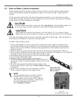
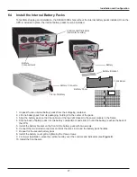
4. Install the two battery packs and secure with the two brackets supplied.
5. Connect the two slotted battery cables.
6. Attach the battery cover plate and the two front bezels.
7. Connect the supplied external battery cabinet cables to either set of
connectors on the rear of the external battery cabinet, then to the rear
of the UPS.
8. The UPS is now equipped with additional backup battery runtime.
For approximate battery run times, refer to
Table 6 - Battery run times
in this manual.
9. Do NOT turn on the battery cabinet circuit breaker at this time.
Please complete the remainder of the installation first.
Support Base With
Spacers for External
Battery Cabinets
NOTE
UPS automatically detects the number of standard
batteries that are connected. The configuration
program maybe used to setup the UPS for operation
with non-standard external batteries. Instructions for
using the configuration program follow in
8.0 - Configuration Program
.
13
UPS and
External Battery Cabinet
+
BA
TTE
RY
CO
NNEC
TO
R
BA
TTE
RY
CONNE
C
TIO
N
CIRCUIT BREAKE
R
+
+
+
Summary of Contents for S4K6U10000
Page 1: ...S S4K6U10000 power availability On Line UPS 120 208V 120 240V USER MANUAL...
Page 2: ......
Page 46: ......
Page 47: ......

