17
EN
MASTERYS BC+ 60-80 kVA - Ref.: IOMMASBCXX0F-EN 00
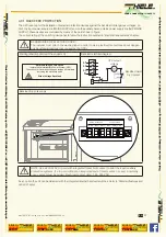
4.3.1 BACKFEED PROTECTION
The UPS is set up for the installation of external protection devices against the backfeed of dangerous voltages, on
both the input power supply line (MAINS SUPPLY) and on the auxiliary backup mains power supply line (AUX MAINS
SUPPLY); these devices are controlled by means of the card shown in figure.
The current rating of the switching device has to follow the instruction outlined in 'Electrical requirements' chapter.
DANGER! RISK OF ELECTRIC SHOCK!
The installer must attach the warning label in order to warn electrical technicians about danger-
ous backfeed situations (not caused by the UPS).
Warning label (supplied with the equipment)
Backfeed electrical diagram
Before working on this circuit
- Isolate the Uninterruptible Power System (UPS)
- Then check for Hazardous Voltage between all terminals
including the protective earth
Risk of Voltage Backfeed
B
L1
L2
L3
N
UPS output
voltage
Backfeed Card
Dry Contact
Backfeed trip coils supply
COM2 NC2
NO2
NO1 COM1 NC1
MAINS BACKFEED
AUXBACKFEED
NOTE: Use a 220-240 V trip coil with integrated travel limit contact to pilot the input/auxiliary
protection systems. If a trip coil without an integrated end of travel contact is used, a normally
open contact must be added. Electrical contact data: 1.6 A 250 V AC.
As an option the unit can be delivered with the integrated internal backfeed switches. Refer to 'Standard features and
option' chapter.
YOUR CONNECTION TO SAFETY
Thiele KG
• V
orderer W
einberg 26 • D-71522 Backnang • T
el.: +49 (0)7191 3560-0
• Fax.: +49 (0)7191 3560-19
• www
.thiele-kg.de
Thiele KG
• V
orderer W
einberg 26 • D-71522 Backnang • T
el.: +49 (0)7191 3560-0
• Fax.: +49 (0)7191 3560-19
• www
.thiele-kg.de
YOUR CONNECTION TO SAFETY
klick to
www
u-s-v
YOUR CONNECTION TO SAFETY
klick to
www
ACDC-DCDC
YOUR CONNECTION TO SAFETY
klick to
www
SYSTEME
YOUR CONNECTION TO SAFETY
klick to
www
CONTACT
YOUR CONNECTION TO SAFETY
klick to
www
CALLBACK


