background image

12

MODULYS GP Green Power 2.0 

range from 25 to 200 kVA - Ref.: IOMMODGPXX05-GB  01

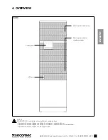
4. OVERVIEW

4-2

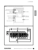
  System with manual bypass and input, aux mains, output switches

Wiring diagram

U4

U5

U6

U7

U3

U2

U1

U8

X20

2

1

0

Q6

PE

400Vac 3Ph+N 50Hz

INPUT MAINS

X10

AUXILIARY MAINS

400Vac 3Ph+N 50Hz

X40

F1

G1

BATTERY

X50

400Vac 3Ph+N 50Hz

UPS OUTPUT

X3

X4

X14

X5

BY

Q1

Q4

X5

X6

X6

X7

X7

X8

X8

X9

X9

X10

X10

X11

X11

X12

X12

X15

X16

X17

X18

X19

X20

X21

Ethernet network (only for service) 

Option slot 1

Option slot 2

Q4 (Auxiliary mains switch)

Q1 (Input mains switch)

Power supply fuses

Service connection

Remote monitoring service

Hot-swap bypass

Q6 Manual bypass 
and output switch

UPS connections

USB connector (only for service)

Summary of Contents for MODULYS GP 100 kVA

Page 1: ...ower 2 0 range from 25 to 200 kVA Installations und bedienungsanleitung DE Manual de instalaci n y uso ES Manuel d installation et d utilisation FR Installation and operating manual GB Manuale di inst...

Page 2: ...ent of long periods of storage or UPS inactivity SOCOMEC may at its own discretion opt for the repair of the product or the replacement of faulty or defective parts with new parts or with used parts o...

Page 3: ...5 1 MAINS AND AUXILIARY MAINS CONNECTED SEPARATELY 16 5 3 EXTERNAL BATTERY CONNECTION 17 5 4 OTHER CONNECTIONS 18 6 CONTROL PANEL 30 7 MENU 32 7 1 DISPLAY OVERVIEW 32 7 2 MENU TREE 35 7 3 MENU FUNCTI...

Page 4: ...mation refer to Technical specification chapter WARNING Connect the protective earth PE conductor before making any other connections NOTE The installer is responsible for implementing the backfeed pr...

Page 5: ...lyte corrodes metals and burns the skin and all parts of the human body WARNING Risk of explosion Avoid short circuits Never place tools or metal objects on the accumulators Wear safety goggles and su...

Page 6: ...onductive inflammable and corrosive items not exposed directly to sunlight The floor must support the weight of the unit and guarantee its stability The unit is designed for indoor non air conditioned...

Page 7: ...d by at least two people The people MUST take position at the sides of the UPS with respect to the direction of movement Do not move the unit by putting pressure on the front door When moving the unit...

Page 8: ...S residual current detectors Load leakage currents are to be added to those generated by the UPS and during transitory phases power failures and power returns short current peaks may occur If loads wi...

Page 9: ...PS Then check for Hazardous Voltage between all terminals including the protective earth Risk of Voltage Backfeed B L1 L2 L3 N Inverter voltage Output Dry Contact 1 2 Input Backfeed 3 4 Bypass Backfee...

Page 10: ...Power cables and control cables MUST NEVER be installed in the same duct WARNING Risk of electromagnetic interference between battery cables and output cables Common Mains Load N N Battery Control cab...

Page 11: ...oor Slots for power modules or battery modules Slots for power modules only NOTE MODULYS GP is available in three different configurations System with manual bypass and input aux mains output switches...

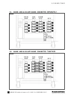
Page 12: ...RY MAINS 400Vac 3Ph N 50Hz X40 F1 G1 BATTERY X50 400Vac 3Ph N 50Hz UPS OUTPUT X3 X4 X14 X5 BY Q1 Q4 X5 X6 X6 X7 X7 X8 X8 X9 X9 X10 X10 X11 X11 X12 X12 X15 X16 X17 X18 X19 X20 X21 Ethernet network only...

Page 13: ...INS X10 AUXILIARY MAINS 400Vac 3Ph N 50Hz X40 F1 G1 BATTERY X50 400Vac 3Ph N 50Hz UPS OUTPUT X3 X4 X14 X5 BY Q1 Q4 X5 X6 X6 X7 X7 X8 X8 X9 X9 X10 X10 X11 X11 X12 X12 X15 X16 X17 X18 X19 X20 X21 Ethern...

Page 14: ...manual bypass Power supply fuses Service connection Remote monitoring service Hot swap bypass UPS connections USB connector only for service UPS POWER OFF WARNING The basic version of the cabinet is...

Page 15: ...re in OFF position all the internal battery modules are disconnected the UPS is in maintenance bypass mode refer to Operating modes chapter all UPS power modules are disconnected Check the presence of...

Page 16: ...1 EXTERNAL BATTERY MAINS SUPPLY AUX MAINS SUPPLY OUTPUT PROTECTIVE EARTH TERMINAL 5 CONNECTIONS 5 1 MAINS AND AUXILIARY MAINS CONNECTED SEPARATELY 5 2 1 EXTERNAL BATTERY MAINS SUPPLY AUX MAINS SUPPLY...

Page 17: ...requirements chapter WARNING Cabling errors with inversion of battery polarity may cause permanent damage to the equipment Reassemble the plastic terminal block protection N B N B UPS BATTERY CABINET...

Page 18: ...nit is stable 5 4 2 Power module electrical diagram 5 4 3 Bypass module electrical diagram X2 F1 F2 80 A F3 F4 F5 80 A F6 F7 F8 80 A 400 Vac 3ph N 50 Hz INPUT MAINS 400 Vdc 3 W INPUT BATTERY 400 Vac 3...

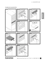
Page 19: ...MODULYS GP Green Power 2 0 range from 25 to 200 kVA Ref IOMMODGPXX05 GB 01 ENGLISH POWER MODULE INSERTION WARNING Ensure the module is installed in the correct position 5 CONNECTIONS 1 2 3 4 7 10 6 9...

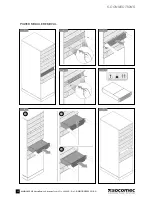
Page 20: ...20 MODULYS GP Green Power 2 0 range from 25 to 200 kVA Ref IOMMODGPXX05 GB 01 POWER MODULE REMOVAL 5 CONNECTIONS 1 2 3 4 7 6 5 A B C...

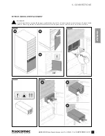
Page 21: ...SH BYPASS MODULE REPLACEMENT WARNING It is only possible to remove the bypass module when the unit is in normal mode or in maintenance bypass mode refer to operating modes chapter Before removing the...

Page 22: ...NS 7 8 9 6 5 WARNING The screws provide protective bonding and avoid unauthori sed bypass removal Tighten the screws to ensure the bonding protection DANGER Failure to observe this safety instruction...

Page 23: ...Battery packs have to be moved individually Never handle the entire battery module or more than one battery pack NOTE Up to six battery modules can be installed in the unit NOTE Battery modules must...

Page 24: ...24 MODULYS GP Green Power 2 0 range from 25 to 200 kVA Ref IOMMODGPXX05 GB 01 5 CONNECTIONS 4 7 5 6 8 A B C...

Page 25: ...25 MODULYS GP Green Power 2 0 range from 25 to 200 kVA Ref IOMMODGPXX05 GB 01 ENGLISH 5 CONNECTIONS 9 10 A B C D 11 12 A B...

Page 26: ...26 MODULYS GP Green Power 2 0 range from 25 to 200 kVA Ref IOMMODGPXX05 GB 01 5 CONNECTIONS 13 14 15 A D B E C F...

Page 27: ...27 MODULYS GP Green Power 2 0 range from 25 to 200 kVA Ref IOMMODGPXX05 GB 01 ENGLISH BATTERY MODULE REPLACEMENT 5 CONNECTIONS 3 2 A D B E C F 1...

Page 28: ...28 MODULYS GP Green Power 2 0 range from 25 to 200 kVA Ref IOMMODGPXX05 GB 01 5 CONNECTIONS 6 5 4 A B C...

Page 29: ...29 MODULYS GP Green Power 2 0 range from 25 to 200 kVA Ref IOMMODGPXX05 GB 01 ENGLISH 5 CONNECTIONS 7 8 9 10 11 A B C...

Page 30: ...munication Control panel luminous status bar indicator Colour Status Green Load protected on inverter Flashing green UPS in startup procedure phase or battery test Yellow Load supplied with warning By...

Page 31: ...anel extraction 6 3 Display ESC BUTTON Exits current page aborts operations UP BUTTON Scrolls up through the available menus values DOWN BUTTON Scrolls down through the available menus values ENTER BU...

Page 32: ...lert is active Enter ALARMS menu to display the complete alerts list Status bar color Flashing green yellow red no information available Green load supplied Flashing green start procedure in progress...

Page 33: ...lert bar overwrites the icons when active 7 1 5 Mimic panel 7 1 4 Additional Icons Bypass mode or Eco Mode not possible Commissioning Code not inserted refer to Menu functions de scription paragraph o...

Page 34: ...reen level reached is continuous other levels ashing Battery charging Bar colour green level reached is continuous other levels ashing Battery charged Bar colour green Battery discharged Battery open...

Page 35: ...S SUBUNIT CONTROLS ALARMS RESET PROCEDURES FUNCTIONING MODE BATTERY TEST SETTINGS PREFERENCES LANGUAGE DATE AND TIME BUZZER DISPLAY PASSWORD UPS SETTINGS OUTPUT BATTERIES TRANSFORMER BACKFEED PARALLEL...

Page 36: ...en a password is required a virtual keyboard is displayed The default password is SOCO ALARMS menu This menu displays all pending UPS alerts Use the ALARMS RESET command in the COMMANDS menu to reset...

Page 37: ...rent Risk of damage to load or batteries HISTORY LOG menu EVENT LIST menu it shows the list of UPS alerts and events that have occurred Last 150 events can be displayed Press UP DOWN to scroll the lis...

Page 38: ...USB services Choose UPGRADE LANGUAGES or enter the menu MAIN MENU SERVICE UPGRADE LANGUAGES When on a parallel system the SYS unit has to be selected beforehand on the mimic panel page Step 4 The lis...

Page 39: ...menu MAIN MENU COMMANDS UPS PROCEDURES Select Automatic Stop Procedure and press ENTER Wait approx 2 minutes for the UPS shutdown NOTE The controlled shutdown of each server connected to the LAN can b...

Page 40: ...osition 1 Wait for the display to switch on Close the external battery breaker fuses Put or keep switch Q6 Q5 in position 0 The battery must be charged for at least ten hours Once ten hours have elaps...

Page 41: ...after the overload disappears When the voltage generated by the inverter goes outside the limits due to a major overload or a fault on the inverter When the internal temperature exceeds the maximum va...

Page 42: ...ried out on the system so that the necessary actions can be perfor med by service personnel without having to disconnect the power supply to the load 9 5 OPERATION WITH MOTOR GENERATOR GENSET The UPS...

Page 43: ...t a zero potential contact to terminals IN1 and IN1 of the ADC card The UPS power OFF input is normally disabled It can be enabled only by SOCOMEC service personnel Connection of the generator If your...

Page 44: ...of the battery for analysis The expected life time of the batteries is very much dependent on operating conditions number of charging and discharging cycles load rate temperature NOTE Batteries must...

Page 45: ...Nominal output voltage 15 20 if GENSET is used Bypass input frequency Hz 50 60 2 selectable 8 if GENSET is used Stored energy mode of operation Number of battery blocks VRLA From 18 18 to 24 24 Enviro...

Page 46: ......

Page 47: ......

Page 48: ...386 1 5807 860 Fax 386 1 561 11 73 info si socomec com SPAIN 836 3RZHU RQWURO QHUJ IILFLHQF Solar Tel 34 93 540 75 75 Fax 34 93 540 75 76 info es socomec com UNITED KINGDOM Power Control Energy Effici...

Reviews: