background image

28

MASTERYS

 BC 60-80 kVA - Ref.: IOMMASBCXX06-EN  06

7. CONNECTIVITY AND COMMUNICATION OPTIONS

As each channel is independent, simultaneous connections can 
be made to satisfy the different levels of signalling and remote 
monitoring.

See the options paragraph to access the detailed functions of 
the cards installed in the slots.

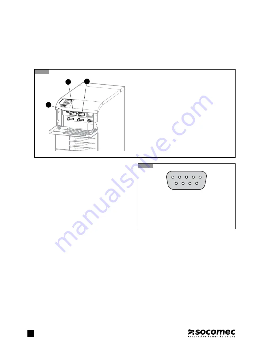
Key for pin RS232/485 C1

1 Not connected

2 RX for RS232

3 TX for RS232

4 Data +

5 GND for RS232

6 Data − 

7 Reserved 

8 Not connected

9 +12 V

7.1-1


7.1-2


Key 

C1

  Serial connector RS232/485

S1

  Options slot 1

S2

  Options slot 2

S2

S1

C1

3

4

5

2

1

8

9

7

6

7.1. MULTI-LEVEL 

COMMUNICATION

MASTERYS BC can manage a variety of serial, contact and Ethernet communication channels simultaneously. 

The various cards and signalling accessories are inserted in the two standard communication slots. This gives MASTERYS BC 
immediate interfacing and integration flexibility as soon as the unit is installed with no need for trained personnel.

Summary of Contents for MASTERYS BC 60 kVA

Page 1: ...Asennus ja k ytt ohje FI Manuel d installation et d utilisation FR Manuale di installazione e uso IT Installatie en bedieningshandleiding NL Dokumentacja Techniczno Ruchowa PL Manual de instala o e f...

Page 2: ...riods of storage or UPS inactivity SOCOMEC may at its own discretion opt for the repair of the product or the replacement of faulty or defective parts with new parts or with used parts of equivalent q...

Page 3: ...PERATION WITH EXTERNAL MANUAL BYPASS OPTIONAL 16 4 ACCESS TO CONTROLS 17 4 1 IDENTIFYING SWITCHES AND INTERFACES 17 4 2 SWITCH FUNCTIONS FOR THE 60 80 KVA RANGE 18 5 MIMIC PANEL 19 5 1 BASIC MIMIC PAN...

Page 4: ...d on external access points if present between the said isolators and the UPS In particular the label must be attached to the external AC input line isolation service backfeed insulation Keep this man...

Page 5: ...TY STANDARD 1 2 DESCRIPTION OF SYMBOLS USED ON LABELS ATTACHED TO THE UNIT All precautions and warnings on labels and plates inside and outside the equipment should be observed DANGER HIGH VOLTAGE BLA...

Page 6: ...ept apart and the sender or recipient should be contacted All packaging must be recycled in compliance with existing legislation in the country where the system is installed 2 UNPACKING AND INSTALLATI...

Page 7: ...generated by the UPS and during transitory phases power failure and power return short current peaks may occur If loads with high leakage current are present adjust the differential protec tion It is...

Page 8: ...conditions or due to installations downstream e g ground fault not detected and protected high dispersion of a phase or the IT system it will be necessary to install either devices that disconnect the...

Page 9: ...abelled OUTPUT L12 L22 L32 N2 2 4 7 Connect the external battery cables if present to the terminals labelled EXTERNAL BATTERY B2 B2 B1 B1 refer to paragraph 2 9 2 4 8 Guide any control cables from the...

Page 10: ...e a space of at least 20 cm between the power and the control cables avoid parallel channelling over long distances choose cables crossing at 90 instead 2 4 9 2 4 12 2 4 10 2 4 13 2 4 11 E E A power c...

Page 11: ...res between the UPS units This gives enough room for an external battery cabinet to be inserted beside each UPS 2 7 3 Power connections The power supply to each unit must be protected as indicated in...

Page 12: ...bus cable C Single UPS magneto thermal switch if a separate auxiliary power source is used add a magneto thermal switch for each UPS D Ext bypass magneto thermal switch E 1 Output switch connect sign...

Page 13: ...e cables in question are supplied with the UPS in the case of standard parallel setups or are attached to the parallel kit in the case of a later system upgrade Parallel con guration must only be acti...

Page 14: ...ng errors with inversion of battery polarity may cause permanent damage to the equipment Replace the terminal board protection If using cabinets not supplied by the UPS manufacturers it is the install...

Page 15: ...erated by the inverter goes outside the limits due to a major overload or fault on the inverter when the internal temperature exceeds the maximum value allowed Battery mode In the event of a mains fai...

Page 16: ...ed with the appropriate procedure the load is powered directly from the maintenance bypass while the UPS is separated from the power supply and can be switched off This operating mode can be selected...

Page 17: ...Serial connector RS232 485 S Mimic panel S1 Options slot 1 S2 Options slot 2 Q2 Input switch Q3 Output inverter switch Q4 Auxiliary mains Input switch Q5 Output maintenance bypass switch Q3 S2 S1 S C...

Page 18: ...e inverter continuous power supply Q5 connects the output directly to the auxiliary mains input manual bypass Positions Q3 closed 1 and Q5 open 0 this is the position for normal operation of the UPS f...

Page 19: ...that identifies the condition of the power supply to the load C Alphanumeric information that uses a menu layout to provide details on any alarms that may occur and on the measurements controls and pa...

Page 20: ...1 2 Meaning of light bar status The light bar B figure 5 1 1 provides immediate indication of the condition of the power supply to the load Red power supply not present or shutdown imminent Yellow pow...

Page 21: ...ised into menus and submenus as shown in the diagram to access a menu press the ENTER key To return to the higher level press ESC key Use the and keys to scroll the information available at a particul...

Page 22: ...5 INVERTER ALARM Inverter fault A26 BATT CHARGER ALM Battery charger fault A29 BYPASS ALARM Bypass fault A30 OVERLOAD STOP The duration of the overload has inhibited the bypass A38 EXTERNAL ALARM1 Sig...

Page 23: ...up shutdown reset alarms to the UPS and to select the operating mode Commands can also be sent for diagnostic purposes by means of the extended commands menu if enabled in the configurations menu The...

Page 24: ...LE Set if battery is present YES NO if YES SET BATTERY TYPE Selects the type of batteries used Sealed SET BATTERY CAPACITY Sets the battery capacity in Ah 9 5 1000 Ah SET CHARGER TYPE Selects the type...

Page 25: ...cation of the equipment serial number which is displayed in the next message by pressing ENTER WARRANTY CODE SN 0000000000 Inserting the code does not limit the availability of equipment functionality...

Page 26: ...load and stops the UPS and the battery charger Activate the stop procedure from the commands menu on the mimic panel wait approx 2 minutes for shutdown the controlled shutdown of any servers is manag...

Page 27: ...above before activating this switch 6 1 5 Return to normal mode Set switch Q4 Q2 to position 1 input mains ON Set the external battery switches to position 1 battery circuit closed Activate the start...

Page 28: ...or RS232 3 TX for RS232 4 Data 5 GND for RS232 6 Data 7 Reserved 8 Not connected 9 12 V 7 1 1 7 1 2 Key C1 Serial connector RS232 485 S1 Options slot 1 S2 Options slot 2 S2 S1 C1 3 4 5 2 1 8 9 7 6 7 1...

Page 29: ...m 2 OUT 2 ESD activation 1 OUT 3 Battery low or imminent stop 2 OUT 4 ESD activation 1 IN 1 1 ESD 1 IN 2 External alarm A39 2 IN 3 2 External alarm A40 2 7 2 ADC CARD To be installed in one of the two...

Page 30: ...OFIBUS adapter allows UPS models to be connected to a Profibus network 7 6 SOFTWARE OPTIONS A large number of SW solutions can be adopted on MASTERYS BC thanks to its advanced communication facilities...

Page 31: ...07 OVER TEMPERATURE The technical plant temperature is higher than the maximum value recommended Check the ventilation or air conditioning system in the UPS room A08 MAINTEN BYPASS The output disconne...

Page 32: ...g efficiency and avoid equipment downtime It is strongly advisable to give due consideration to any instructions to perform preventive maintenance displayed automatically with alarm message M29 refer...

Page 33: ...perating conditions When necessary fans should be replaced as per specifications by SOCOMEC 8 3 3 Capacitors The equipment houses electrolytic capacitors used in the rectifier and inverter section and...

Page 34: ...rmer 9 4 SEPARATE AUXILIARY POWER SUPPLY This allows the use of an auxiliary energy source other than the primary mains power supply in the event of outage 9 5 EXTERNAL BACKFEED PROTECTION External de...

Page 35: ...A AC1 9 7 PROTECTION ON A UPS WITHOUT AUXILIARY MAINS SUPPLY Activating UPS protection on the mimic panel access the SERVICE menu on the mimic panel see the SERVICE menu section and set the SET BACKF...

Page 36: ...s nominal output voltage 15 from 10 to 20 selectable if generator is used Nominal power kW 54 72 Overload 25 C Vin 380 Vbat 216 2 10 minutes 1 minute kW 67 5 81 90 108 Crest factor 2 7 Voltage distort...

Page 37: ......

Page 38: ......

Page 39: ......

Page 40: ...386 1 5807 860 Fax 386 1 561 11 73 info si socomec com SPAIN 836 3RZHU RQWURO QHUJ IILFLHQF Solar Tel 34 93 540 75 75 Fax 34 93 540 75 76 info es socomec com UNITED KINGDOM Power Control Energy Effici...

Reviews: