Sno-Way 28V Series Owner'S Manual Download Page 23

22

13. Lower plow onto blocking.

14. Adjust each disk shoe assembly by removing disk 

shoe mounting pin and adding or subtracting washers on
the top or bottom of the disk shoe mounting bracket as
required according to measurements taken in step #11
(See Figure 2-17).

Figure  2-17

15. After the disk shoe position is properly adjusted, 

place washers on the disk shoe stem - above the disk
shoe mounting bracket, and below the retaining pin - to
remove all up and down movement of the disk shoe in the
bracket. Failure to do this will result in excessive wear of
the holes in the disk shoe mounting bracket and will also
result in bending the stem of the disk shoe.

16. After the wing disk shoe adjustment is complete, 

lower the plow to the ground. If this disk shoe adjustment
is correct, the shoes and the wearstrips will all be on the
ground at the same time, if not, repeat steps #11 to #15.

17. Move the wings forward and rearward. If the wing 

wearstrips and the center wearstrips are not on the
ground at all times recheck the position of the wing pivot
tubes. The tubes must be vertical, if they are not vertical,
the center disk shoe will need to be adjusted.

Float Limiter Adjustment

IMPORTANT: 

The disk shoes must be properly

adjusted prior to adjusting the float limiter. If the
shoes are not properly adjusted, the float limiter
adjustment cannot be properly made.

1. With the vehicle and snow plow on a smooth, level 

surface move the wings forward into the “scoop” position
and lower the plow to the ground.
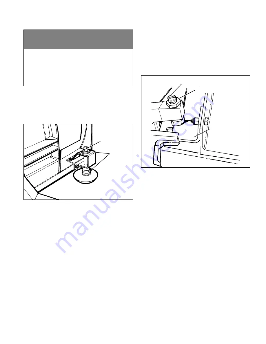
Figure  2-18

2. Loosen the 5/8" jam nut on the top of the float limiter 

adjusting screw.

3. Using the screwdriver slot in the top of the float limiter 

adjusting screw, turn the adjusting screw down until the
hex head of the adjusting screw touches the surface of
the replaceable wear plate.

4. Turn the adjusting screw up two turns to provide a 

gap between the wear plate and the head of the adjusting
screw for proper float allowance.

5. While holding the adjusting screw driver slot, to 

prevent turning of the adjusting screw, tighten the 5/8”
jam nut to lock the adjusting screw and prevent turning of
the adjusting screw during operation.

6. Repeat on other side.

c

WARNING

Keep hands and feet clear of wings and center
section when setting blocking and lowering
plow. Moving or falling assemblies could result
in serious injury.

FAILURE TO HEED CAN RESULT IN INJURY 

OR DEATH.

WASHERS

PIN

JAM NUT

ADJUSTING SCREW

REPLACEABLE
WEAR PLATE

Summary of Contents for 28V Series

Page 1: ...OWNER S MANUAL 28V SERIES SNOW PLOW WITH EIS FOR PLOW SERIAL NUMBERS AFTER 28VG100100 28VD100302 97101116C 2006 Sno Way International...

Page 2: ...king Lots 7 Mounting Snow Plow To Vehicle 8 Installing The Cylinder Lock Clamp 10 Removing Snow Plow From Vehicle 11 Plow Storage 12 TROUBLESHOOTING 13 Introduction 13 Troubleshooting Quick Reference...

Page 3: ...the Pump Serial Number in the space provided below as a handy record for quick reference The Power Pack Serial Number is located on the A Frame near the front on the driver s side the blade serial num...

Page 4: ...m p h when plowing Excessive speed may cause serious injury and damage of equipment and property if an unseen obstacle is encountered while plowing ALWAYS position blade so it does not block path of h...

Page 5: ...id sends current to the power unit motor to cause the power unit to pump hydraulic fluid Hydraulic fluid under pressure is directed through the C valve to the lift cylinder causing it to extend and ra...

Page 6: ...ed together using the control switches on the controller Operating the forward combination switch on the controller will extend both wings in the scoop position Operating this combination will energiz...

Page 7: ...ty light weight HP Lithium based grease 6 For extremely cold weather plowing continuous sub zero operation an alternative is to remove the grease fittings and fill the grease cavity with SAE 140 gear...

Page 8: ...e pavement If down pressure decreases results if a valley or low spot is encountered by the blade more down pressure is applied to lower side of the lift cylinder and the blade will follow the contour...

Page 9: ...s down To raise the pins press up For Gravity Plows To lower the pins place plow in float and push up on light bar To raise the pins press up 2 Plug in power harness and remove controller from truck c...

Page 10: ...OFF Upper hitch pins will snap into place Figure 1 3 5 Unplug plow from control 6 Disengage both jack stand pins by pulling on handles Raise the jack stand and engage the bottom pin by pushing on the...

Page 11: ...against cylinder c WARNING Failure to properly connect plow lights to vehicle light harness will prevent plow lights from functioning Follow proper procedure to connect light harnesses and test lights...

Page 12: ...male connectors on the truck light harness together See Figure 1 9 Figure 1 9 5 Turn Down Pressure ON and then OFF 6 Rotate pin handles up straight out to unlock main pins See Figure 1 11 Figure 1 11...

Page 13: ...lt place a board or piece of plywood etc under the jackstand to prevent the jackstand foot from sinking into the ground 2 To avoid corrosion during storage coat the exposed chrome portion of the lift...

Page 14: ...following information available A Date Snow Plow was originally installed B Power Pack Model Number C Power Pack Serial Number D Controller Serial Number E Blade Model Number F Blade Serial Number G P...

Page 15: ...to Dealer Pick up tube filter plugged See Maintenance Section Pick up tube is not submerged in fluid See Maintenance Section Machine failure Refer to Dealer Weak battery and or charging system Refer...

Page 16: ...oid valve sticking Cycle raise and lower system to un stick valve Unit lifts but does not hold second action Dirt or debris in check valve Refer to Dealer Check valve spring broken Refer to Dealer Flo...

Page 17: ...ective Refer to Dealer Crossover relief valve defective or sticking Refer to Dealer Low or no current available at extend or retract solenoid valve Refer to Dealer Angle cylinder defective allowing mo...

Page 18: ...g temperature See Maintenance Section Defective Wing Cylinder Refer to Dealer Dirt or debris in Solenoid Valve Refer to Dealer Blade wings will not hold position fold rearward Defective or dirt debris...

Page 19: ...s with a good quality HP Lithium based grease NOTE For extremely cold weather plowing continuous sub zero operation an alternative is to remove the grease fittings and fill the grease cavity with SAE...

Page 20: ...is will help ensure maximum life and maxi mum performance from the pump assembly 1 Lower plow assembly to ground put vehicle in park and turn off engine Turn hand held controller off 2 Remove two 2 se...

Page 21: ...in the cylinders 13 Reconnect hydraulic fittings in their correct position and torque to 20 25 lb ft If unit utilizes o ring and jam nut type connectors tighten jam nut to 15 20 lb ft 14 Fill the hyd...

Page 22: ...6 Raise plow and place suitable blocking under the plow to allow at least eight inches 8 of clearance from the bottom of the center disk shoe to the ground 7 Lower plow onto blocking 8 Adjust center d...

Page 23: ...disk shoe will need to be adjusted Float Limiter Adjustment IMPORTANT The disk shoes must be properly adjusted prior to adjusting the float limiter If the shoes are not properly adjusted the float lim...

Page 24: ...he frame 1 Raise the plow to the full UP position 2 Place suitable blocking under A frame of plow to allow at least 6 of clearance from the blade to the ground IMPORTANT Make sure to position blocking...

Page 25: ...ck to make sure that the spring is installed as illustrated with open end of top loop facing vehicle See Figure 2 22 3 Using a 15 16 socket wrench through the holes in the bottom plate of the main fra...

Page 26: ...25 NOTES...

Page 27: ...with asterisk are in lb in Grade 1 Grade 2 Grade 5 5 1 or 5 2 Grade 8 or 8 2 Lubricateda Dryb Lubricateda Dryb Lubricateda Dryb Lubricateda Dryb SIZE lb ft lb ft lb ft lb ft lb ft lb ft lb ft lb ft 8...

Page 28: ...27 HYDRAULIC SCHEMATIC GRAVITY...

Page 29: ...28 HYDRAULIC SCHEMATIC DOWN PRESSURE...

Page 30: ...29 WIRING SCHEMATIC GRAVITY...

Page 31: ...30 WIRING SCHEMATIC DOWN PRESSURE...

Page 32: ...Way will not be liable for any expense not related to defects in materials and workmanship The attachment of product to or upon a vehicle including any necessary modification of product or vehicle is...

Reviews: