IQH3A IQ 3U Modular Enclosure
www.snellgroup.com
Installation
Issue 2 Rev 2
Page 29
©
2014 Snell Limited
3.13.4 Replacing a Module in a Live Environment
Snell recommends that the power supply is switched off and the mains connections are
removed before performing the previous operations. However, in a live environment, this may
not be possible and you can remove and install modules without switching the power off.
3.14 Replacement of the Cooling Fan Assembly
The cooling fan assembly is located on the rear panel of the 3U enclosure and may be easily
replaced without removing the rack from its mounting position or removing any cable
connections.
There are two versions of the Fan Unit assembly:
•
Part No. FGAN IQH3FANA fitted with a 2-pin in-line connector assembly.
•
Part No. FGAN IQH3FANB fitted with a 3-pin PCB connector assembly.
To remove the fan assembly:
1.
Switch off the unit’s power supplies and remove the IEC power cables.
2.
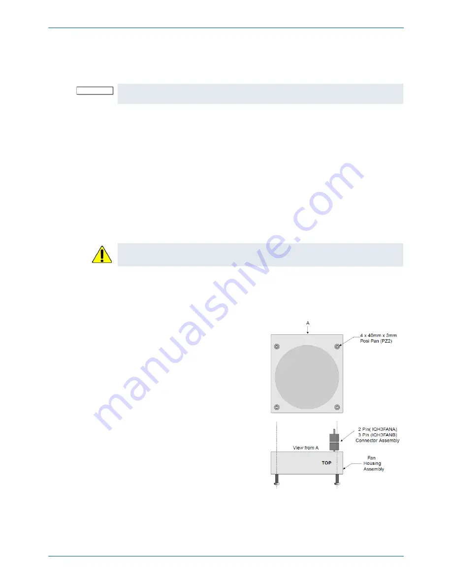
Remove the four 40 mm x 3 mm posi-pan retaining screws.
3.
Withdraw fan assembly and disconnect the fan power supply by pulling apart the 2-pin
in-line (IQH3FANA version) or 3-pin PCB mounted (IQH3FANB version) connector
assembly. This releases the complete fan assembly.
To replace the fan assembly:
Important:
It cannot be guaranteed that there will be no disturbance to the operation of other modules
in the enclosure when you replace a module without first powering down the enclosure.
Ensure that the fan blades have stopped rotating before attempting removal.
1.
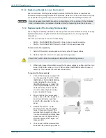
Connect the fan power supply of the
new fan assembly (Part No. FGAN
IQH3FANA or FGAN IQH3FANB) by
mating together the 2-pin in-line
(IQH3FANA version) or 3-pin PCB
mounted (IQH3FANB version) con-
nector assembly. Ensure that the
connector assembly and warning
label is located at the top.
2.
Ensure that the fan power supply
cable is clear of the fan blades and
any other obstructions and then
locate the fan assembly on the rear
panel.
3.
Refit the four 40 mm x 3 mm
Posi-Pan screws into the tapped
holes in the rear of the unit. This
secures the fan assembly to the unit.
It is recommended that initially these
screws are not fully tightened; they
should be tightened in stages, in a
diagonal order.
4.
You can now refit the power cables
and switch the power supply units on.


