background image

MC1000/MC1000-IQ/MC2000/MC2000-IQ

RollCall Control Panel System Setup Screens

Issue 1 Rev 8

Page 93

© 2015 SAM

10. RollCall Control Panel System Setup Screens

This section details all of the screens, menu lists, options, and controls available for setting up 
the unit from the RollCall Control Panel.

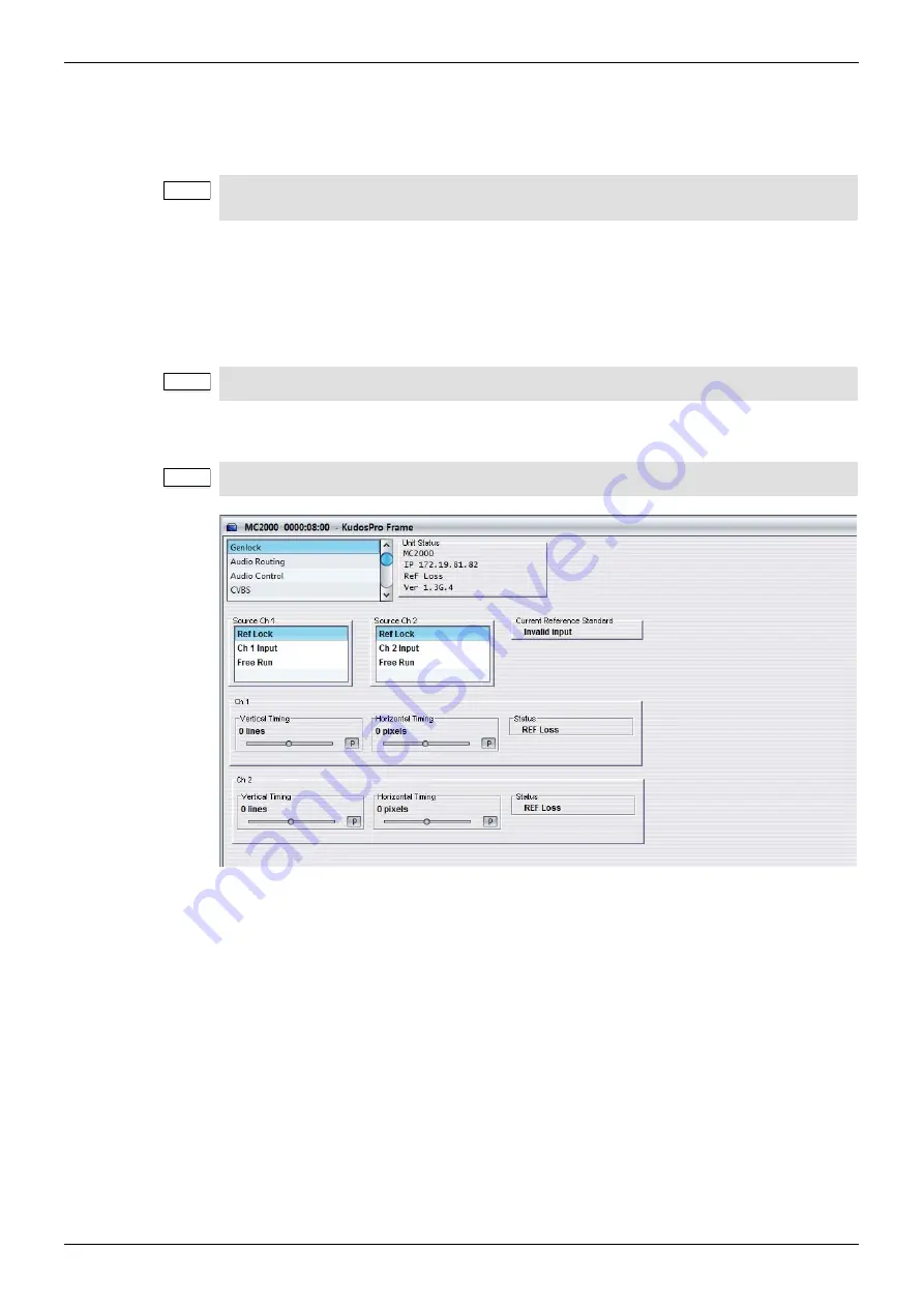
10.1 Genlock

The Genlock screen provides controls that lock the output video clock to the genlock source 
(input or reference) regardless of the video standard. If the genlock source and the video 
output are the same frame rate, for example, 50 Hz or 59.94 Hz, Genlock locks the output to 
the vertical phase of the genlock source, giving consistent and repeatable delay.

When attempting to pass non-PCM audio, ensure that Genlock is enabled. If using an 
external reference, it must be clock-locked to the input video.

10.1.1 Source Ch 1 and Ch 2

The Source menu enables you to select options for a genlock source.

Ref Lock:

 Locks the output video to the incoming reference.

Ch 1 Input:

 Locks the output video to the channel 1 input.

Ch 2 Input:

 Locks the output video to the channel 2 input.

Free Run:

 Locks the output video to an internal reference clock.

10.1.2 Current Reference Standard

Current Reference Standard displays the standard of the reference signal. If reference has 
been assigned using the controls but an input signal is not detected on the assigned 
reference input, Current Reference Standard shows “Invalid Input”.

Note:

The screens shown in this section are for guidance and reference only, and may be slightly 
different to those on your unit.

Note:

Lock to input wherever possible. Only lock to an external reference if necessary.

Note:

If Genlock is set to Free Run, non-PCM audio will always be corrupt.

Summary of Contents for KudosPro MC1000

Page 1: ...Standards Converter KudosPro MC1000 IQ Single channel Motion Compensated Standards Converter with Two IQ Module Slots KudosPro MC2000 Dual channel Motion Compensated Standards Converter KudosPro MC200...

Page 2: ...ubject to change without notice and does not represent a commitment on the part of SAM The software described in this manual is furnished under a license agreement and can not be reproduced or copied...

Page 3: ...ch an qualifiziertes Personal L Phase N Nulleiter N Nulleiter L Phase E Schutzleiter E Schutzleiter Explicaci n de los S mbolos de Seguridad ste s mbolo refiere al usuario informaci n importante conte...

Page 4: ...KKE FJERNES INGEN BRUGER SERVICERBARE DELE SERVICE M KUN UDF RES AF FAGL RTE PERSONER F 0 J 0 F J Han stik Hun stik F rklaring av S kerhetssymboler Denna symbol h nvisar anv ndaren till viktig informa...

Page 5: ...de est sempre devidamente ligada terra e que as liga es alimenta o est o correctas O sistema de alimenta o do equipamento deve por raz es de seguran a possuir liga o a terra de protec o e liga o ao NE...

Page 6: ...LUE lead connected to N Neutral Conductor Laser Safety This product operates with Class 1 laser products Ventilation Although the unit is constructed to meet normal environmental requirements ensure t...

Page 7: ...ual conform to the EMC requirements for and are intended for use in the controlled EMC environment for example purpose built broadcasting or recording studios and the rural outdoor environment far awa...

Page 8: ...0 and MC2000 23 4 2 Rear Panel View MC1000 IQ and MC2000 IQ 23 4 3 Input and Output Connections 23 4 3 1 Audio Connection Pin Numbers Option 25 4 3 2 Fiber Connectivity 26 4 4 Control Connections 26 4...

Page 9: ...7 9 1 Memory Select 43 7 9 2 Save Memory 43 7 9 3 Recall Memory 43 7 9 4 Reset to Defaults 44 7 9 5 Factory Reset 44 7 9 6 Memory Name 45 7 10 Logging 46 7 11 Status 46 7 12 Calibration MC1000 MC2000...

Page 10: ...imecode Entry 82 8 8 10 Timecode Entry 82 8 8 11 Timecode Load 82 8 8 12 On Timecode Loss 82 8 8 13 Non Drop Frame 82 8 9 Metadata 83 8 9 1 Closed Captions 83 8 9 2 Multi line WST 84 8 10 Memory 87 8...

Page 11: ...1 Input Source 110 11 2 Output 111 11 2 1 Output Standard 111 11 2 2 Freeze 111 11 2 3 Legalization 112 11 2 4 Test Patterns 112 11 2 5 Blanking 112 11 2 6 Default Output 112 11 2 7 Scrolling Caption...

Page 12: ...ate Conversion SD Composite Video 157 A 4 MC2000 Frame Rate Conversion HD SDI to SD Composite Video 158 A 5 Using Decoded Dolby E Audio when Converting Video 159 A 5 1 From the Front Panel 159 A 5 2 F...

Page 13: ...fitted before shipping Any IQ modules fitted are controlled using RollCall and cannot be controlled from the front panel of the MC1000 IQ MC2000 IQ unit For a full list of compatible IQ modules and r...

Page 14: ...channel Optional one channel MC1000 MC1000 IQ or two channels MC2000 MC2000 IQ of Dolby E decode transcode Dolby E guard band alignment Up to two IQ modules can be fitted within the unit MC1000 IQ MC2...

Page 15: ...S B1 and B2 can be used as outputs Other connectors are present on the rear panel such as CVBS C1 and C2 and CVBS D1 and D2 but these cannot be used 1 6 2 MC1000 MC1000 IQ Audio Processing Note The MC...

Page 16: ...SDI outputs B1 and B2 are used for video processing channel B MC2000 only The CVBS I O is restricted by design only CVBS A1 A2 B1 and B2 can be used as inputs to the MC2000 and only CVBS C1 C2 D1 and...

Page 17: ...er The second decode transcode path Decode 2 Encode 2 in the block diagram is only available as embedded audio on SDI outputs B1 and B2 and can be routed to any AES or analog audio encoder It is not p...

Page 18: ...ard Audio AES 4 x balanced AES inputs via 25 way D type Not MC1000 IQ MC2000 IQ 4 x unbalanced AES inputs via 4 x BNC Audio Analog 4 x stereo analog inputs via 25 way D type Signal Outputs Serial digi...

Page 19: ...b s motion compensated standards conversion Up down and cross conversion Conversion Linear motion compensated Conversion processing Still process Detects still images and applies an aperture with full...

Page 20: ...ap and phase invert feature Non PCM processing features pair level routing and delay compensation Dolby E data is passed with a delay to match the video and with co timed audio frame drop or repeat Do...

Page 21: ...et enhancement levels Low Med High Super Custom H Gain and H Noise rejection levels Advanced Vertical Frequency Band Selection Low Med High Five preset enhancement levels Soft 2 Soft 1 Normal Sharp 1...

Page 22: ...alled rack shelf and secure the unit using the front rack ears 3 3 Ventilation Ensure that there is a free flow of air at the front rear and sides of the unit to dissipate the heat produced during ope...

Page 23: ...d as i o can be used as inputs or outputs Label Description Connector SDI In 1 2 3 4 SDI inputs 4 x BNC SDI Out A1 A2 B1 B2 SDI outputs 4 x BNC Analog Audio In option Analog audio inputs 1 x 25 way D...

Page 24: ...IEC Power B PSU input secondary 1 x 3 pin IEC Note If one of the reference connectors is not in use it must be fitted with a 75 Ohm BNC terminating plug If not terminated correctly genlock performance...

Page 25: ...3 Ch 7 in 16 Ch 7 out 16 Ch 3 out 16 GND2 4 GND2 4 GND2 4 GND3 17 GND3 17 GND3 17 Ch 6 in 5 Ch 6 out 5 Ch 2 out 5 Ch 6 in 18 Ch 6 out 18 Ch 2 out 18 Ch 5 in 6 Ch 5 out 6 Ch 1 out 6 Ch 5 in 19 Ch 5 out...

Page 26: ...iber option is fitted on the rear panel do not remove the safety covers from the option slots Note If all the optional SFP connectors A1 A2 B1 and B2 are fitted as receivers they will not be available...

Page 27: ...information for each processing channel On a menu list the display shows the menu options and a thumbnail image of the current output signal On a menu list with a menu option selected for example Proc...

Page 28: ...reen when selected Home button HOME Press to return to the default Home screen at any time Shortcut Alphanumeric buttons The Shortcut buttons provide direct access to the corresponding menus The Alpha...

Page 29: ...ng channel Unit name IP address Input and output status Audio status You can return to the Home screen at any time by pressing the HOME button 6 3 Selecting Processing Channels MC2000 MC2000 IQ only Y...

Page 30: ...l for fine tuning values in small increments The Alphanumeric buttons are useful for quick entry of a specific value 6 7 1 Adjusting Values with the Control Knob 1 Navigate to the menu option slider t...

Page 31: ...sor blinks once before pressing the button again To enter a space between characters press button 0 To enter a special character such as the symbol press button 9 To delete a character press the Back...

Page 32: ...video input output slots if the CVBS option is fitted Composite encoding and decoding options will have been chosen at the time of product purchase Y C decoding is also available The composite capabi...

Page 33: ...this control when chroma levels are low compared to luminance This may occur when using YC installations or composite from RF links CTI The Chroma Transient Improver CTI examines the input video data...

Page 34: ...this slot then select Done 3 From the CVBS menu select Format 4 Choose the format of the composite output then select Done For example to create a PAL composite output on slot C1 where the converted o...

Page 35: ...e the AES audio for each output 7 3 2 Analog Group 1 2 Group 1 2 Selects where to route the analog audio for each output group Note The AES and analog audio menus are only available if the CVBS option...

Page 36: ...input source from either the balanced or unbalanced input connections if fitted 7 4 2 Analog In ADC Headroom Pair 1 4 Adjusts the ADC headroom level for each analog input pair The adjustment range is...

Page 37: ...s Reference Status shows the standard of the reference signal If reference has been assigned using the controls but an input signal is not detected on the assigned reference input Current reference st...

Page 38: ...s and certain hardware restrictions The Dolby E option variants allowed are as follows For more information about the Dolby decoder and transcoder see the KudosPro Dolby Application Note under the Sup...

Page 39: ...n correct alignment Encoder Version Shows the version number of the Dolby encoder The Dolby E decoder and encoder both have their own software version installed which is independent from the rest of t...

Page 40: ...Shows the unit s MAC address IP Configuration Enables you to specify whether the unit is to use a DHCP or a static IP address For information about setting static and DHCP IP addresses see page 41 IP...

Page 41: ...ct IP Netmask 8 Enter 255 255 255 0 using the Alphanumeric buttons then select Done 9 When all addresses are set you must apply the changes To do this Select the Apply IP Changes button then select Do...

Page 42: ...2000 MC2000 IQ Only Current Channel shows which channel is currently being controlled The chosen current channel appears on the HDMI output and on the front panel thumbnail image 7 8 3 Brightness The...

Page 43: ...iguration Network IP Gateway Network IP Netmask RollCall Unit Name Settings stored in the system memories include CVBS encoder or decoder settings if fitted MC1000 MC2000 only Dolby option settings if...

Page 44: ...Any saved settings for IP Address IP Netmask and IP Gateway are also lost when performing a factory reset The unit returns all three to their default settings which are as follows IP Configuration DH...

Page 45: ...lphanumeric button 1 to 8 repeatedly until the desired character appears If the next character you want is on the same button as the present one wait until the cursor blinks once before pressing the b...

Page 46: ...l number of the unit PSU A PSU B The PSU voltage Module 1 Temperature The current temperature of the FPGA module Dolby Ch 1 and Ch 2 Whether the Dolby channel is available 7 12 Calibration MC1000 MC20...

Page 47: ...he Front Panel on page 29 8 1 Home The Home screen shows status of the unit in use You can access the Home screen at any time and from any menu by pressing the HOME button 8 2 Input The Input menu ena...

Page 48: ...choose the type of pattern displayed on the output picture You can choose from Off Black Ramp and Bars 8 3 5 Default Output On input signal loss select black to set output to black default or pattern...

Page 49: ...f Default 700mV 721mV 735mV 746mV 8 3 9 Logo Control Logo control enables static or animated graphics to be keyed on to the video output of a channel Logo files are uploaded to the KudosPro unit using...

Page 50: ...1080i A specifier of the form _ index indicates that this file is part of a multi file sequence for an animated logo Any non negative decimal value may be used for index The files in a sequence are so...

Page 51: ...e current channel Select a logo by clicking on the logo name The selected logo is highlighted Click on None Selected if no logo is required for the channel H Position Set the position of the left edge...

Page 52: ...Saturation Adjusts the color saturation The adjustment range is 6 dB to 6 dB in 0 2 dB steps The preset value is 0 dB Black Level Adjusts the black level The adjustment range is 100 mV to 100 mV The...

Page 53: ...t from 0 to 192 The preset value is 0 Mode Preset controls Low Sets Level to 2 and Noise Rejection to 15 for the selected frequency band Medium Sets Level to 4 and Noise Rejection to 15 for the select...

Page 54: ...d source material Low 1 Recommended for over enhanced source material Normal Optimum setting for balancing detail and alias High 1 Recommended for slightly soft source material High 2 Recommended for...

Page 55: ...ally with Auto mode or manually with the Threshold slider Luma Adjusts the noise reduction applied to the luminance signal The adjustment range is 0 to 7 The preset value is 0 Chroma Adjusts the noise...

Page 56: ...se between automatic and manual filtering In Auto mode the background noise level is measured and the threshold set to give a good compromise between noise reduction and picture softness In Manual mod...

Page 57: ...artifacts on moving repetitive patterns Enhanced Film Applies an aperture with full progressive frequency response where the input is film transported by an interlaced video rate input with cadence en...

Page 58: ...the source material contains known continuous 2 3 2 3 Start Hour Sets the starting hour for the timecode when 2 3 Source is set to Input Timecode The adjustment range is from hour 0 to hour 23 in one...

Page 59: ...of the output picture does not change just how much of the active picture remains visible The portion that is cropped is either default black in Output Crop mode or is replaced by a secondary video pi...

Page 60: ...bar Key Source options that are not suitable are grayed out from the selection list for example the source is the not the same output standard as the video it is being keyed into or SFP 2 is actually...

Page 61: ...justment range is 50 to 50 in steps of 1 The preset value is 0 8 6 5 Scaler Config Presets If no input aspect signaling is available and the conversion required is always from a known input aspect rat...

Page 62: ...le line rather than a 720 sample line If the outgoing content requires a 702 sample line select the check box This introduces an additional H scaling factor of 702 720 resulting in a slight horizontal...

Page 63: ...ion Menus Issue 1 Rev 8 Page 63 2015 SAM 8 6 5 4 HD Cross Conversion Select Standard Preset PB pillarbox v crop vertical crop ana anamorphic 8 6 5 5 Up Conversion Select Standard Preset LB letterbox P...

Page 64: ...ARC 8 6 6 1 Input Signaling Source Input Signaling Source lists the available supported aspect signaling standards SMPTE 2016 SMPTE ST 2016 1 Format for Active Format Description AFD and Bar Data L23...

Page 65: ...the aspect ratio conversion if the input aspect signaling cannot be detected SD Input Format The SD input format Normal Default 4 3 aspect ratio Anamorphic Horizontally squeezes a widescreen image to...

Page 66: ...ng the aspect ratio 14 9 Can scale either a 4 3 image for viewing on a 16 9 screen or a 16 9 image for viewing on a 4 3 screen This is a compromise in order to maintain the aspect ratio of the image b...

Page 67: ...ns show the ARC conversions possible using input signaling and a combination of SD Output Format and Conversion Scaling controls For each of the conversions there are four columns of images The first...

Page 68: ...MC1000 MC1000 IQ MC2000 MC2000 IQ Channel Operation Menus Issue 1 Rev 8 Page 68 2015 SAM SD Output Format Anamorphic 16 9 8 6 8 2 HD Cross Conversion...

Page 69: ...0 MC1000 IQ MC2000 MC2000 IQ Channel Operation Menus Issue 1 Rev 8 Page 69 2015 SAM 8 6 8 3 Up Conversion SD Output Format has no effect as output is HD 8 6 8 4 Down Conversion SD Output Format Normal...

Page 70: ...MC1000 MC1000 IQ MC2000 MC2000 IQ Channel Operation Menus Issue 1 Rev 8 Page 70 2015 SAM SD Output Format Anamorphic 16 9...

Page 71: ...it the screen so that the whole white area fills the screen This will override Fit to width 14 9 and Fit to height setting so that all three give the same output result It also overrides the SD Output...

Page 72: ...ed in the Force Mode Config SMPTE 2016 list The list contains 16 AFD codes for coded frame AR of 4 3 and eight AFD codes for a coded frame AR of 16 9 Delete Disables embedding of SMPTE 2016 output sig...

Page 73: ...TE Force generates an output SMPTE RP 186 95 signal with scanning system information that matches what is selected in the Force Mode Config SMPTE RP 186 list 4 3 and 16 9 are available but the actual...

Page 74: ...in the Force Mode Config ETSI list The list contains eight AFD codes When Output Format is set to AFD Force generates an output ETSI EN 300 294 signal that is modified to carry VI scanning system info...

Page 75: ...signaling mode is set to Force this control offers a list of 16 AFD codes for coded frame AR of 4 3 and the same AFD codes for a coded frame AR of 16 9 Selecting one will generate a SMPTE 2016 output...

Page 76: ...oss Audio is unavailable or invalid 8 7 1 2 Process Pair 1 8 For each of the output pairs 1 8 you can select the audio source to be passed to each audio processor on the Audio Shuffle screen For each...

Page 77: ...Pairs 1 8 Status The Status list shows the status of the audio output pairs The audio status display information is as follows P PCM L Loss N Non PCM 8 7 2 Control The Control menu enables you to adju...

Page 78: ...elay controls enable you to set delay pair offsets and the audio delay relative to the video delay Global Delay Pair Offsets Global delay offsets for pair 1 8 Pair 1 8 Adjusts the audio delay offset f...

Page 79: ...govern output pair combinations P PCM N non PCM S silence T test tone F forced mute silence Invert Phase Enables you to invert the phase of the left and right audio channels This control is useful fo...

Page 80: ...frame or non drop frame 8 8 1 Source HD SD The Source controls enable you to choose a timecode type from the input LTC or VITC for HD and VITC ATC LTC or ATC VITC for SD For HD video standards the sup...

Page 81: ...which VITC is placed when the channel output is 525 The range is from line 11 to line 17 in one line steps The default is line 14 8 8 6 Output Line 625 The Output Line 625 slider selects the output li...

Page 82: ...imecode should behave if input timecode cannot be detected Freeze On timecode loss the output timecode will freeze at the last valid detected input value until the valid input returns Free Run On time...

Page 83: ...ich are extracted and encoded as an output line 21 signal Closed captions are automatically detected in the input video and the detected format shown in the Status window For closed captions to be emb...

Page 84: ...ext subtitle transcoding is supported from WST to RDD 08 by taking the decoded bytes from the WST signal and inserting them into the payload within the SDP see below Transcoding from RDD 08 to WST is...

Page 85: ...Type SMPTE RDD08 default SMPTE 2031 RDD08 2031 Output Packet Enable Off Default RDD08 2031 Output Packet Enable RDD08 2031 Output Packet Type SMPTE RDD08 default SMPTE 2031 SMPTE RDD08 RDD08 Output L...

Page 86: ...he second RDD 08 packet and so on 2 If SMPTE2031 conversion is selected then the first 5 lines selected on the input are encoded in the 2031 packet Each single WST line corresponds to one SMPTE2031 pa...

Page 87: ...s Conversion options such as Still Process Signaling parameters SDI output audio routing per processing channel PCM audio controls gain delay L R swap Timecode settings Closed caption processing choic...

Page 88: ...enter a special character such as the symbol press button 9 To delete a character press the Back button To save a memory name From the Save Memory menu select Save Memory 8 11 RollCall The RollCall me...

Page 89: ...setup screens contain all of the menu lists options and controls available for setting up the unit To open the system setup screens At the top of the RollCall network tree right click the product name...

Page 90: ...rame rate and format conversions for each processing channel To open the channel operation screens On the RollCall network tree double click the required channel name The Input screen is displayed 9 3...

Page 91: ...sion The Unit Status window on a channel operation screen shows the current channel and the input output and audio status The audio information line shown here as Analog 2 PCM cycles through the audio...

Page 92: ...formation about the RollCall Control Panel template screens and controls see RollCall Control Panel System Setup Screens on page 93 and RollCall Control Panel Channel Operation Screens on page 110 To...

Page 93: ...nal reference it must be clock locked to the input video 10 1 1 Source Ch 1 and Ch 2 The Source menu enables you to select options for a genlock source Ref Lock Locks the output video to the incoming...

Page 94: ...he reference signal The adjustment range is one output line in one line steps The preset value is 0 Horizontal Timing Adjusts the horizontal timing of the output signal with respect to the reference s...

Page 95: ...oose where to route the AES audio for each output 10 2 2 Analog Output 1 2 You can choose where to route the analog audio for each output group Note The AES and analog audio menus are only available i...

Page 96: ...log audio signal 10 3 1 1 Analog ADC Headroom Pair 1 4 Adjusts the ADC headroom level for each analog input pair The adjustment range is 12 dB to 24 dB The preset value is 18 dB 10 3 1 2 AES Input Typ...

Page 97: ...llCall Control Panel System Setup Screens Issue 1 Rev 8 Page 97 2015 SAM 10 3 2 1 Analog DAC Level Pair 1 4 Adjusts the DAC audio output level for each analog output pair The adjustment range is 12 dB...

Page 98: ...Y C decoding is also available The composite capability is determined by the number of processing channels and certain hardware restrictions The composite variants allowed are as follows Product Compo...

Page 99: ...en the input video has chroma bandwidth limitations Pedestal When turned on allows the composite source NTSC only to be treated as if a pedestal is present NTSC Hue Adjusts the NTSC hue to correct ton...

Page 100: ...to the Dolby frame rate is enabled but a change to the Dolby program format is not possible For example if the incoming video is at 50 Hz with 5 1 2 Dolby audio when the MC1000 MC1000 IQ MC2000 MC200...

Page 101: ...version kudospro Product Dolby option codes allowed Description MC1000 MC1000 IQ Dolby E single channel option One set of Dolby modules decode and transcode MC2000 MC2000 IQ Dolby E single channel opt...

Page 102: ...belled 45 02 pair 1 Packet Type Selects a method of data mapping for output SMPTE 2020 VANC packets A SMPTE 2020 2 2008 B SMTE 2020 3 2008 Input Status Shows the status of the Dolby encoders and if th...

Page 103: ...teway Shows the current IP gateway Current IP Netmask Shows the current IP netmask IP Configuration Enables you to specify whether the unit is to use a DHCP or a static IP address For information abou...

Page 104: ...st apply the changes To do this Click Apply IP Changes The system updates and saves the changes made in the Ethernet menu 10 6 1 2 Setting a DHCP IP address 1 From the System Menu select Network 2 Und...

Page 105: ...sen current channel appears on the HDMI output and on the front panel thumbnail image 10 7 2 LCD Display Lock Front Panel Locks all of the front panel controls to prevent accidental changes to the uni...

Page 106: ...work IP Netmask RollCall Unit Name Settings stored in the system memories include CVBS encoder or decoder settings if fitted MC1000 MC2000 only Dolby option settings if fitted Genlock selection and ad...

Page 107: ...both system and channel level All controls and user memories are reset to their preset values The default settings for IP Configuration is to set the unit to DHCP Any saved settings for IP Address IP...

Page 108: ...options Serial Number Uptime how long the unit has been powered up in days hours minutes seconds PSU 1 State PSU 2 State Reference Standard 10 10 Status The Status screen shows the status of the unit...

Page 109: ...r A and B Luma Gain Adjusts the composite luminance signal Chroma Gain Adjusts the composite chrominance signal Y C Chroma Gain Adjusts the component Y C chrominance signal Save Saves the gain setting...

Page 110: ...eration screens The MC2000 MC2000 IQ units have channels 1 2 available 11 1 Input The Input screen enables you to specify a video input source 11 1 1 Input Source Input Source lists the available vide...

Page 111: ...put The Output screen enables you to apply various settings and adjustments to the video output signal 11 2 1 Output Standard Standard Specifies the output standard of a conversion Current Output Stan...

Page 112: ...inimizing hue change and raising apparent brightness Legalizer choices are Off Default 700mV 721mV 735mV 746mV 11 2 4 Test Patterns The Test Patterns list enables you to choose the type of pattern dis...

Page 113: ...under the Support tab at http www snellgroup com products conversion and restoration conversion kudospro Logo Up loader To upload logos onto the MC1000 MC1000 IQ MC2000 MC2000 IQ run the logo upload a...

Page 114: ...ir respective index es by numerical value Leading zeros do not affect the sort order and it is not required that the index values are contiguous however all images in a multi file sequence must have t...

Page 115: ...selected logo is highlighted Click on None Selected if no logo is required for the channel H Position Set the position of the left edge of the logo image from the left of the screen as a percentage o...

Page 116: ...ier Proc Amp enables you to correct video inconsistencies such as contrast Enable Enables the Proc Amp Contrast Adjusts the contrast The adjustment range is 6 dB to 6 dB in 0 2 dB steps The preset val...

Page 117: ...and high frequency bands and to create a custom setting if required Enable Enables the enhancer Mode Preset controls Low Sets Level to 2 and Noise Rejection to 15 for the selected frequency band Medi...

Page 118: ...r over enhanced source material Normal Optimum setting for balancing detail and alias Sharp1 Recommended for slightly soft source material Sharp 2 Recommended for very soft source material Detail Dete...

Page 119: ...ode the background noise level is measured and the threshold set to give a good compromise between noise reduction and motion blur In Manual mode increasing the Threshold value allows for pictures wit...

Page 120: ...to extract the maximum resolution from interlaced sources while format or standards converting The benefits of this processing are prominent on static logos and computer generated overlays Enhanced M...

Page 121: ...timecode Automatic The cadence detection circuit automatically detects the cadence This is useful when the source material contains mixed cadences Input Timecode Defines the relationship between time...

Page 122: ...Control Panel Channel Operation Screens Issue 1 Rev 8 Page 122 2015 SAM 11 5 ARC Aspect Ratio Control ARC enables you to determine the aspect ratio of a picture from a range of options or to adjust th...

Page 123: ...eo picture into the cropped area as defined using the Output Crop Position controls see see section 11 5 3 2 When selected the source of the second video picture is becomes available in the Sidebar Ke...

Page 124: ...election list for example the output of the second channel in a single channel product or SFP input if no SFP rear is fitted Sidebar Key Source options that are not suitable are grayed out from the se...

Page 125: ...line select the check box This introduces an additional H scaling factor of 720 702 resulting in a slight horizontal stretch This control only has an effect on SD inputs 11 5 5 2 SD Output is 702 SD...

Page 126: ...IQ RollCall Control Panel Channel Operation Screens Issue 1 Rev 8 Page 126 2015 SAM 11 5 5 4 HD Cross Conversion PB pillarbox v crop vertical crop 11 5 5 5 Up Conversion LB letterbox PB pillarbox v cr...

Page 127: ...C 11 5 6 1 Input Signaling Source The Input Signaling Source box lists the available supported aspect signaling standards SMPTE 2016 SMPTE ST 2016 1 Format for Active Format Description AFD and Bar Da...

Page 128: ...h will force the aspect ratio conversion if the input aspect signaling cannot be detected SD Input Format The SD input format Normal Default 4 3 aspect ratio Anamorphic Horizontally squeezes a widescr...

Page 129: ...e see section 11 5 8 for a list of possible ARC conversions using input signaling and a combination of SD Output Format and Conversion Scaling controls 11 5 7 2 SD Output Format When the output video...

Page 130: ...1000 MC1000 IQ MC2000 MC2000 IQ RollCall Control Panel Channel Operation Screens Issue 1 Rev 8 Page 130 2015 SAM 11 5 8 1 SD Cross Conversion SD Output Format Normal 4 3 SD Output Format Anamorphic 16...

Page 131: ...MC1000 IQ MC2000 MC2000 IQ RollCall Control Panel Channel Operation Screens Issue 1 Rev 8 Page 131 2015 SAM 11 5 8 2 HD Cross Conversion 11 5 8 3 Up Conversion SD Output Format has no effect as output...

Page 132: ...MC1000 MC1000 IQ MC2000 MC2000 IQ RollCall Control Panel Channel Operation Screens Issue 1 Rev 8 Page 132 2015 SAM 11 5 8 4 Down Conversion SD Output Format Normal 4 3 SD Output Format Anamorphic 16 9...

Page 133: ...retched to fit the screen so that the whole white area fills the screen This will override Fit to width 14 9 and Fit to height setting so that all three give the same output result It also overrides t...

Page 134: ...what is selected in the Force Mode Config SMPTE 2016 list The list contains 16 AFD codes for coded frame AR of 4 3 and eight AFD codes for a coded frame AR of 16 9 Delete Disables embedding of SMPTE 2...

Page 135: ...ut Format is set to SMPTE Force generates an output SMPTE RP 186 95 signal with scanning system information that matches what is selected in the Force Mode Config SMPTE RP 186 list 4 3 and 16 9 are av...

Page 136: ...t match what is selected in the Force Mode Config ETSI list The list contains eight AFD codes When Output Format is set to AFD Force generates an output ETSI EN 300 294 signal that is modified to carr...

Page 137: ...E 2016 output signaling mode is set to Force this control offers a list of 16 AFD codes for coded frame AR of 4 3 and the same AFD codes for a coded frame AR of 16 9 Selecting one will generate a SMPT...

Page 138: ...o to the required embedded audio output 11 6 1 Input Pairs Input Pairs shows the input sources available to be routed 11 6 1 1 Source Embedded 1 8 Routes the available embedded audio sources to the ei...

Page 139: ...95 11 6 1 2 Status The Status box shows the status of the audio input pairs The audio status display information is as follows PCM Audio is PCM Mute Audio is muted Tone Audio is a test tone DolbyE Au...

Page 140: ...1 dB steps The preset value is 0 dB 11 7 2 Tone Frequency The Tone Frequency slider adjusts the tone frequency The adjustment range is 0 1 kHz to 10 kHz in 0 1 kHz steps The preset value is 1 kHz Poin...

Page 141: ...sts the audio delay offset for each of the eight audio channel pairs The adjustment range is 40 ms to 200 ms in 1 ms steps The preset value is 0 ms The Total box shows the current total pair delay 11...

Page 142: ...udio Routing screen 11 8 2 Output Pairs Status Shows the status of the audio output pairs Pair 1 8 For each of the output pairs 1 8 you can select the audio source to be routed to the output Note Cert...

Page 143: ...io channels This control is useful for dealing with input audio discrepancies 11 8 4 Control Tone Makes the audio input source a test tone Silence Mutes the audio input source Use Routing Routes the a...

Page 144: ...d or if Generate mode is selected For SD video inputs VITC ATC LTC and ATC VITC timecode data formats are supported For SD video outputs the timecode data format is fixed to VITC This is present in al...

Page 145: ...3 Status The Status box reports which type of embedded timecode is detected within the video input to this processing channel If no valid timecode is detected None is displayed 11 9 2 Processing The...

Page 146: ...t in the Input Trigger Entry field To set a value In the Output Timecode Entry field enter the required value and click S to set To return to the preset value click P 11 9 2 4 Generator When timecode...

Page 147: ...line on which VITC is placed when the channel output is 525 The range is from line 11 to line 17 in one line steps The default is line 14 Output Line 625 Selects the output line on which VITC is plac...

Page 148: ...ge 148 2015 SAM 11 10 Metadata The Metadata screen enables you to control a set of closed captions and teletext subtitle information Incoming SD or HD closed captions and subtitles are converted to th...

Page 149: ...n the Status window For closed captions to be embedded in the output video they must be enabled User control for on which line to embed CEA 708 is provided but CEA 608 is always fixed at line 21 11 10...

Page 150: ...of WST to be encoded SMPTE2031 allows only 5 lines of WST to be encoded 625 Input 625 Output You can select which input lines of WST are encoded on the output see instructions for SD VBI line setup be...

Page 151: ...contain within them the original source SD line number information The input line selection refers to this line number and not the ANC packet position line number HD Input 625 Output You can select wh...

Page 152: ...gs such as noise reduction parameters proc amp settings and enhancer parameters Conversion options such as still process Signaling parameters SDI output audio routing per processing channel PCM audio...

Page 153: ...saved in a memory location To recall a memory 1 In the Memory Select column select the memory you want to recall 2 Click Recall Memory The recalled settings are applied 11 11 3 Reset to Defaults Reset...

Page 154: ...eld type a new name for the unit 2 To save the name click S To return the name to its preset value click P 11 13 Logging The Logging screen defines what parameter information is made available to a lo...

Page 155: ...fy that the status display shows 1080 59i as the input If the status display shows input loss review steps 1 to 3 to ensure you have correctly connected and routed the source 6 Press the OUTPUT Shortc...

Page 156: ...ure you have correctly connected and routed the source 9 Press CH SELECT button until the Channel 1 LED is illuminated 10 Press the OUTPUT Shortcut button 11 Select Output Standard 1080 59i then selec...

Page 157: ...A then select Done 4 Press the HOME button 5 Verify that the status display shows 625 50i as the input If the status display shows input loss review steps 1 to 3 to ensure you have correctly connected...

Page 158: ...the status display for channel 1 shows 1080 50i as the input If the status display shows input loss review steps 1 to 4 to ensure you have correctly connected and routed the source 7 Press the OUTPUT...

Page 159: ...ss the SYSTEM Shortcut button 2 Select Dolby Dolby Ch 1 Decoder Source Embedded 1 then select Done 3 Press the HOME button 4 Press CH SELECT until the channel 1 LED is illuminated 5 Press the AUDIO Sh...

Page 160: ...ed 1 then select Done 3 Press the HOME button 4 Press CH SELECT until the channel 2 LED is illuminated 5 Press the AUDIO Shortcut button 6 Select Routing Pair 1 Source Dolby Encoder then select Done N...

Page 161: ...reset is also useful as it puts the unit under test into a known state prior to starting the fault finding process Factory Reset recalls the unit s default memory settings at both system and channel...

Page 162: ...2 V Onboard regulation provides the necessary supply voltages required by the various sub assemblies The unit operates on one power supply only but has dual supplies for redundancy If you suspect a PS...

Page 163: ...CE Shortcut button b Select Video Enhance Nonlinear Enhancer Enable then select Done Make sure that Noise Reduction and all Proc Amp settings are disabled when testing a conversion You can turn these...

Page 164: ...lected B 3 4 Composite Input Problems MC1000 MC2000 Only If you are routing a composite signal via one of the CVBS decoders Check that you have a valid SD composite source You can create a valid compo...

Page 165: ...ing Flowchart Important Always keep the software up to date A software upgrade may clear a bug identified and fixed in a later release For information about how to upgrade your software see Software U...

Page 166: ...To test for this Apply a known good source that is the same video standard as the problematic source you can set up an unused KudosPro channel with a video pattern and test tone If the problem is doe...

Page 167: ...consider Each embedded pair EMB1 2 to EM15 16 has its own individual tone generator AES can be balanced or un balanced MC2000 IQ balanced AES only Only four pairs of AES can be processed Analog audio...

Page 168: ...el units is to use the internal timecode generator of one channel to test all the other channels B 5 1 1 Testing Timecode Performance Consider the LC4000 this model has four video channels each with a...

Page 169: ...e on page 168 only this time using one of the other three channels as the generator In the following example channel 2 is the timecode generator LC4000 TC Processor Channel 1 set to TC from I P TC Pro...

Page 170: ...problems please contact SAM Customer Support See Contact Details on page 2 Important Upgrading from software version 1 4F 5 or earlier to version 1 5E 6 or later will significantly change the structur...

Reviews: