background image


10 

PARTS ASSEMBLY


The head tracking system consists of two units:  the head tracker itself, which sits atop the listener’s 
head, and the head tracking reference, which is placed in front of the listener.  For simplicity and 
clarity, we will refer to these units as “head-top” and “set-top” respectively.  The “set-top” may well be 
placed atop a television “set” or display screen, or may not, but will always be centred in front of the 
listener. 


Clip

 for head-top 

 
On the Stax headphones, identify the front vs. the back; to do this, look for the 

L

 and 

R

 markings at 

each end of the headband.  Snap the head-top clip onto the top of the headband so that the rectangular 
socket is on the front of the headband. 
 
Although the clip is designed to fit the Stax headband, it can be used with almost any headphones.  To 
attach to a headphone other than the Stax, turn the clip upside-down, place it on the top of the 
headband, and secure it with a rubber band.  The socket should be on the forward side of the headband. 


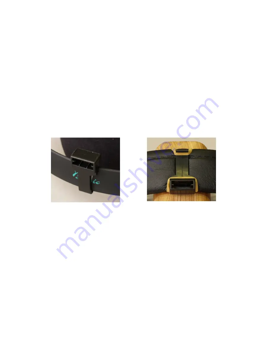
The clip on the Stax headband. 


The clip on another headband. 
    (Shown: Beyer DT 770.) 

Summary of Contents for Realiser A8

Page 1: ...ted from time to time with refinements and new features Likewise the manual is updated to conform with new firmware and to provide additional information Current firmware and the current manual are av...

Page 2: ...le operations 48 Text entry 51 Virtual speaker controls 52 PRIR optimisation 58 HPEQ optimisation 61 PRIR measurement modes and multiplying speakers 63 Azimuth and look angles 72 Tactile outputs 76 Di...

Page 3: ...xposed to rain or moisture does not operate normally or has been dropped Never expose the equipment to rain or a high level of humidity For this reason do not install it in the immediate vicinity of s...

Page 4: ...When connecting the headphone do not place the headphone on your head until you are sure that there is no sound being played When connecting the headphone ensure that the volume is turned down to min...

Page 5: ...card 2 GB or less in size will typically be formatted FAT16 or you can reformat it FAT16 using a computer if necessary Cards larger than 2 GB cannot directly be formatted FAT16 Copy the file onto the...

Page 6: ...ack background no HDMI D white characters on a black background HDMI To enter the ID press MENU then The screen will say ID LINE 1 LINE 2 LINE 3 LINE 4 The junk character is an example and indicates t...

Page 7: ...X SVS enabling future enhancements 7 For the ONE mode speaker delays all conform to the delay measured during the first sweep 8 For the LsRs and LbRb modes the fixed speaker delays are reduced to 8 ms...

Page 8: ...rays 7 The TE screen is no longer momentary it remains until CANCEL is pressed 8 Manual EQ now uses thirty one uniform 500 Hz filter bands except for the last band 9 A CONTROL MENU has been added allo...

Page 9: ...plug to 3 5 mm plug 4 conductor Extension cable 3 5 mm jack to 3 5 mm plug 4 conductor Lanyard orange neck strap Stax SRS 2050 II headphone set includes SR 202 headphones and SRM 252 II drive unit Th...

Page 10: ...lip for head top On the Stax headphones identify the front vs the back to do this look for the L and R markings at each end of the headband Snap the head top clip onto the top of the headband so that...

Page 11: ...the front panel of the Realiser For use with the headphones insert the head top into the clip you have attached to the headphone headband Insert the head top USB connector into the socket with the tr...

Page 12: ...the top of a flat panel display with the tail resting behind the top of the screen There must be a clear line of sight between the head top and the set top at all times during operation Placing the se...

Page 13: ...R jacks Plug the microphones into the L and R jacks Plug the 3 5 mm cable into the jack near the marking SVS The 3 5 mm extension cable can be used if the distance from the listening position to the...

Page 14: ...ser on indicates a remote command received if Realiser off glows dimly in standby mode Sensors the left sensor measures the light level in the room and dims the screen and white LEDs accordingly the r...

Page 15: ...15 LED will light dimly when the head top is communicating with the set top or will light whether operating or not signifying a ready state...

Page 16: ...al user mode LINE OUT 3 and 4 provide the second listener s headphone signal TACTILE outputs for connection of seat shakers can also be used to connect subwoofers PHONES outputs for connection of an e...

Page 17: ...roups of related buttons are considered together POWER toggles between on and standby access to menu for saving system configuration updating firmware blocking remote control and password options With...

Page 18: ...S OH RS LB CB RB SW AUX FEL FER REL RER access to menu for virtual speaker selected ALL restores all virtual speakers from a solo or mute MENU ALL access to menu affecting all virtual speakers MODE se...

Page 19: ...the input meter display pressed once shows a numerical display of the levels of channels 1 4 pressed a second time shows a numerical display of the levels of channels 5 8 pressed a third time returns...

Page 20: ...e enabled or disabled via the CONTROL MENU To access this menu Press The screen will say SAVE SYSTEM CONFIG UPDATE REALISER SW CONTROL MENU PASSWORD OPTIONS Use the v key to Choose CONTROL MENU The sc...

Page 21: ...21 are not automatically saved and the user must SAVE SYSTEM CONFIG for the settings to persist beyond power down...

Page 22: ...tered due to equipment incompatibility an alternate solution is to purchase an HDMI splitter and use one splitter output to connect to the Realiser s input and the other to connect directly to the vid...

Page 23: ...can be used for either purpose via adaptors and both can be used simultaneously with almost all headphone models If using the Stax headphones connect the headphones to the Stax drive unit at the 5 pin...

Page 24: ...s on there has been a boot error turn power off and then on again After boot the Realiser loads Preset 1 see Presets below and displays the Preset 1 ID information for example 1 FACTORY DEF A SMALL 7...

Page 25: ...level falls below 48 dB all ticks are erased In bypass mode the and v keys raise and lower the speaker volume level if the Realiser outputs are connected Mute Pressing the OK key toggles in and out of...

Page 26: ...et or if not set will show the following YEAR 2007 MONTH 07 DAY 07 Step 2 For the line designated by the cursor use the and keys to change the value in that line Use the and v keys to move the cursor...

Page 27: ...values and move to the next channel When finished with I O assignments press EXIT The settings are now in force for the current session only To save the settings press the key The screen will say SAV...

Page 28: ...he side nor back pair placement is optimum for the surround channels in 5 1 material which might be routed to both pairs at appropriate levels or a 5 1 to 7 1 processor might be used But the above is...

Page 29: ...e used in the Realiser computations The elevation values are not used in the computations they are entered as records of the room being captured Note when speaker locations are unknown such as behind...

Page 30: ...de using tiny microphones supplied which fit in the entrance of listener s ear canals If necessary the foam can be compressed with the fingers to make this easier it will expand after insertion The fo...

Page 31: ...ONS Make sure that the cursor is on SAVE SYSTEM CONFIG Press OK and the settings are saved Step 2 The listener sits in the preferred listening position of the room with microphones in ears looking for...

Page 32: ...another calibration run Step 4 After the level calibration press the OK button and the display will revert to the Preset 1 ID Do not change the master volume level until the speaker measurement below...

Page 33: ...mbers appears press OK again These screens are diagnostics which are explained under PRIR Optimisation Then the channels off on screen reappears This screen allows the user to set which channels will...

Page 34: ...nes in your ears and put the headphones on Step 1 Press the HP key to initiate the measurement The screen will say HEADPHONE EQ ROUTINE INITIATED PRESS OK TO PROCEED Step 2 With microphones still in e...

Page 35: ...FILE The screen will say TRANSFER PRIR FILE TRANSFER HPEQ FILE TRANSFER PRES FILE MAKE SD BACKUP Step 2 The cursor can be moved with the and v keys It should already be on TRANSFER PRIR FILE but if no...

Page 36: ...john doe studio b PRIR file is now in both locations 64 and 02 The file in location 64 will be overwritten upon the next PRIR measurement but the copy in location 02 is safe Saving the HPEQ file perma...

Page 37: ...d the same memory location number as was used for the PRIR data In this example that is 01 The screen will say HPEQ File 01 by data erased hp data erased on data erased press to overwrite blinking Ste...

Page 38: ...The screen will identify the PRIR for example 1 FACTORY DEF A SMALL 7 1CH A 20 54 01 APR 09 We now wish to load the newly saved PRIR and HPEQ data into a preset for listening To load a preset press ME...

Page 39: ...in this example but you can use the and v cursor keys to move through the PRIR files to any memory location from 01 to 63 In this example the screen will say PRIR File 01 by john doe at studio b on 1...

Page 40: ...n momentarily inspect the HPEQ ID and date To verify this Step 13 Press the key The screen will momentarily say 2 john doe stax sr 202 A 17 20 15 SEP 08 The Realiser is now set to play Preset 2 The fo...

Page 41: ...RESET 2 SAVE PRESET 2 ERASE PRESET 2 Press OK The screen will say SAVING PRESET All parameter settings are now stored in non volatile preset memory For saving presets to and loading presets from SD ca...

Page 42: ...tep 4 Move your head to experience that the sonic image does not move Solo channels Speaker channels can be played one at a time by using the solo function on the remote control If any channel key on...

Page 43: ...ll say DUAL N DELAY 0 5f 0 0 SCOPE HOLD DEMO OFF Use the and v keys do position the cursor on DEMO Use the and keys to choose OFF or TILT to turn the detector off or on Press OK to save the setting or...

Page 44: ...represents the full experience of being in another environment with room acoustics speaker locations and sound system performance captured for use any time and anywhere The Realiser will provide a sat...

Page 45: ...dphones off speakers on When in bypass mode the screen says BYPASS ACTIVE The Realiser s HDMI output always passes the HDMI input signal through if there is HDMI input and the Realiser is powered on r...

Page 46: ...0 for the left input channel and zero for the rest which can be set as the user wishes The menu shows the first four channels to access the rest press OK The screen will show for the default channel a...

Page 47: ...one or multiple times loops through six modes determining whether the virtual speaker buttons cause solos or mutes and what signal is sent to the Realiser outputs The choice selected appears momentari...

Page 48: ...nal memory to an SD card choose INTERNAL SD The screen will show the last examined internal memory location Use the and v keys to page to the desired file and press OK The screen will say LOADING FILE...

Page 49: ...P4 can be written to an SD card in a single operation Empty internal PRIR and HPEQ locations and empty presets will not be copied Audio functions of the Realiser are suspended during the backup The ro...

Page 50: ...dred HPEQ files You can of course archive more files in subdirectories but only those in the root directory will be loadable Each PRIR file is about 3 1 MB in size each HPEQ file is 32 kB and each PRE...

Page 51: ...the PRIR and HPEQ screens are blank by default but it may be convenient to enter text as a new default For example the owner s name can be set as a default for both entry screens Or a company with man...

Page 52: ...because of the labels The numerical assignment of the measuring Realiser is displayed only because it may shed some light on unusual measured layouts for which inadequate records may have been kept S...

Page 53: ...tion is possible For example if a PRIR contained an overhead virtual speaker and the recording to be played did not include an overhead channel the mix block could be used to direct some or all of the...

Page 54: ...typically used on channel 4 since it is the standard subwoofer channel LFE GAIN Standard practice in multichannel playback is to apply 10 dB of inband gain to the LFE channel If this gain has not bee...

Page 55: ...t noise Another reason would be for analysis of recorded material so that the reverberation of the measured room does not mask small details or errors Very short reverb times such as 5 ms may sound un...

Page 56: ...frames and tenths of frames which is a coarser measure than milliseconds and any amount beyond the tenth of a frame reported in MENU SVS will be reported here To adjust the relative delay press MENU...

Page 57: ...57 1 john doe studio a A 20 01 10 OCT 08 PRX The PROXIMITY setting applies only to the current preset To save it save or re save the preset...

Page 58: ...ddition to the options 1 2 4 and 8 there are the options 1 2 4 and 8 1 is not to be used 2 4 and 8 are again multiple sweeps but there is a pause after each sweep and the next sweep is triggered by pr...

Page 59: ...ranged in order from channel 1 to channel 8 and each channel shows the left ear right ear data pair for the measurements taken at the three head positions For example 89 78 67 78 88 87 89 88 78 45 43...

Page 60: ...ot measured Within channel 1 the left speaker the three sets of inter aural delays are 13 03 and 26 13 inter aural sample delay looking centre 03 inter aural sample delay looking left 26 inter aural s...

Page 61: ...t response and 1 0 denoting a full inversion of the measured response The default values are 1 0 for the low XFACT 0 7 for the middle and 0 3 for the top these values are adjustable via the INVERSION...

Page 62: ...malise the volume between the loudspeaker and headphone rendered systems Adjust REL VOL and if the speaker image in the headphones is offset left or right use the REL BAL control to centre it It is es...

Page 63: ...essing MENU SPK The screen says SAVE AT END YES LOOK ANGLES AZI EXCITATION MENU SPEAKER MODE MENU Setting SAVE AT END to YES means that at the end of the test sequence the measured data is saved as a...

Page 64: ...e CAL values on all other channels so it must always be run on the first round and never on subsequent rounds After the final sweep and the diagnostic screens the channel on off screen reappears This...

Page 65: ...that speaker in that position to all positions by rotating in the chair For the ONE procedure the channel assignments must be as follows See the I O Assignment section earlier in the manual 1 L 2 R 3...

Page 66: ...al system from a real stereo pair of speakers LR is not typically used alone but is used as the first step in the LsRs or LbRb procedures LR measures the left and right speakers and generates a virtua...

Page 67: ...you desire for the virtual surround speakers Typically you will move toward the speakers to obtain wider surround angles The angles for looking left and right while facing rearward are not determined...

Page 68: ...tre back virtual speaker assigned the SW channel tag meaning that the channel 4 input is mapped to it If a real subwoofer is available one will want to do a separate measurement overwriting this virtu...

Page 69: ...ooking toward the rear of the room even though you may be positioned such that the speakers are at 110 If you are using the HT mode for look angles wear the head top unit facing the set top backwards...

Page 70: ...nels on off screen will appear Set it as follows 1 L ON 2 R ON 3 C ON 4 SW ON 5 LS ON 6 RS ON 7 LB ON 8 RB ON This causes eight channels to be saved for a 7 1 PRIR Notes 1 The methods of multiplying s...

Page 71: ...nstead of ALL As noted above LR will create a virtual centre speaker but no harm is done the centre will simply be silent and unnoticed with no centre channel input connected If you prefer that no cen...

Page 72: ...I EXCITATION MENU SPEAKER MODE MENU In the LOOK ANGLES line are these choices AZI azimuth The listener looks directly at the centre left and right speakers and the Realiser takes the look angles to be...

Page 73: ...procedure see below and these angles are used rather than the angles entered manually in the configuration file The pilot tone procedure is especially useful when speakers are hidden behind a screen...

Page 74: ...ng the in ear microphones A headband not provided is used along with the head top clip to hold the head top in position on the head First run the CAL procedure to establish a good measurement level Th...

Page 75: ...cedures to be separate default Set to YES to combine them If combined the subject will hear the pilot tones immediately after the announcer s voice has said Look centre Look left Look right Once the l...

Page 76: ...gain at the Realiser input If not the SW channel would be set to 1 0 and the other channels to 0 3 However the LFE GAIN setting under MENU SW SW vSPKR SETUP1 affects the tactile mix block so if LFE GA...

Page 77: ...priate if the incoming LFE signal is at 0 dB See Bass Considerations for a discussion of LFE boost in various situations However you may wish to vary the level after listening to various programme mat...

Page 78: ...vSPKR SETUP1 L vSPKR SETUP2 Use the v key to choose L vSPKR SETUP1 and press OK The screen will say FILTERS MIX BLOCK LFE GAIN dB LPF MIX The cursor should be on FILTERS if not use the v key to place...

Page 79: ...r especially for sound professionals who need to turn their heads regularly to adjust controls that are out of the headtracking range the mutes can be distracting HOLD is the default because it is pro...

Page 80: ...e designation reported will be IR1 when the switches are up for single user mode and IR2 when the switches are down for dual user mode RANGE The set top has two levels of infrared brightness correspon...

Page 81: ...re than sufficient to provide a stable acoustic image given any actual head movement however rapid To alter the slew rate move the cursor to FILTER and use the and keys to switch between 360 and 180 N...

Page 82: ...ing up the head trackers Here are the setup steps for dual mode operation with two head top units 1 Set the tiny switches on the set top and on both head tops in the down position 2 Plug the second li...

Page 83: ...0 ms to 250 ms Virtually all studio control rooms and living rooms will be well below the 250 ms figure and the corresponding PRIRs will be enjoyed fully But large reverberant spaces will be truncated...

Page 84: ...or playback For example if the measuring Realiser were assigned 1 Left 2 Right 3 Left surround 4 Right surround 5 Centre 6 LFE and the playback Realiser were assigned 1 Left 2 Right 3 Centre 4 LFE 5 L...

Page 85: ...U SVS set DEMO to TILT Now compare the noise level in the speaker with the noise level in the headphones using the tilt function Adjust the headphone volume using the and v keys until the speaker and...

Page 86: ...al delay As noted above the Realiser provides both individual delay for each channel in the virtual channel menus and global delay set here in the SVS menu Latency refers to the inherent delay between...

Page 87: ...ance is a sense of the listener locking in to the sweet spot for listening Input metering As mentioned earlier two meters for headphone level appear when the Realiser volume is adjusted using the and...

Page 88: ...50 ms and the key will increment the end point by 50 ms The default of 800 and 850 represents a 50 ms taper on the full 850 ms capacity of the Realiser The start and end points can be adjusted separat...

Page 89: ...several brief observations let the measurement accumulate for several minutes and press OK This final longer accumulated factor will be the one to use If during the brief trials you get very differen...

Page 90: ...90 display Press OK when finished The setting will apply only until the next power down unless you save it permanently by pressing choosing SAVE SYSTEM CONFIG and pressing OK...

Page 91: ...on and the and keys to set each option to Y or N WRITE TO SD Covers any write to the SD card including PRIR HPEQ and preset files and the BACKUP operation ALTER PRESET Covers loading saving and erasin...

Page 92: ...tection repeat the steps above and enter the existing password into the OLD field The NEW field already contains the default eight spaces press EXIT to complete The Realiser will no longer prompt for...

Page 93: ...arameters press The screen will say SAVE SYSTEM CONFIG UPDATE REALISER SW CONTROL MENU PASSWORD OPTIONS With the cursor on SAVE SYSTEM CONFIG press OK to save The clock calendar accessed by MENU is sa...

Page 94: ...equipment and possibly with a different Realiser In these cases the user may need to consider how LFE level and bass redirection was handled in the measured system and how it is handled in the playba...

Page 95: ...e Realiser Within the PRIR is the 10 dB gain of the virtual subwoofer So the LFE channel is played back in the headphones at 20 dB 10 dB too high The preamplifier or receiver may allow adjustment to r...

Page 96: ...m LFE at Realiser input PRIR SW SW REL VOL Redirection in phones LFE gain upstream LFE gain upstream 10 0 0 none LFE gain upstream LFE gain downstream 0 0 10 none LFE gain upstream LFE gain LF redirec...

Page 97: ...all other active channels and LFE GAIN as shown in the following table LFE GAIN is in dB the MIX BLOCK coefficients are gain factors 1 0 representing no reduction and 0 3 representing 10 dB As in the...

Page 98: ...g the LFE into one or more main channels within the Realiser Four possibilities exist as detailed in the tables below The LFE levels in the headings refer to the LFE level output by the preamplifier a...

Page 99: ...efault assignments for these numbered channels but these can be reconfigured by the user as described in the I O Assignment section of this manual P1 L5 L1 LS L P2 L1 L3 L C P3 L1 L2 L R P4 L5 L6 LS R...

Page 100: ...cs peak hold time backlight illumination and dropout detection parameters The screen will say LEVEL METER SETUP PHASE METER SETUP DROP METER SETUP HP LIMITER SETUP LEVEL METER SETUP Brings up this men...

Page 101: ...Turns the dropout detector ON or OFF A dropout is declared when a signal drops below the range of the meter all segments are off the average signal just prior to the drop is above a certain level thre...

Page 102: ...x RCA type Frequency range 20 Hz 20 kHz 1 dB Input level maximum 2 8 V rms 10 dBV Output level maximum 1 4 V rms Signal to noise ratio 105 dB A weighted Latency single user mode 16 ms Power consumpti...

Page 103: ...103 If you have questions or have experienced any difficulties please contact us at info smyth research com...

Page 104: ...RESEARCH RESEARCH RESEARCH Smyth Research LLC 1270 Avenida Acaso Unit A Camarillo CA 93012 USA 1 805 482 5630 Smyth Research Ltd Enterprise House 4 Balloo Avenue Bangor County Down Northern Ireland B...

Reviews: