7
Ser
vice
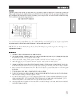
SERVICE CHART
Before servicing or making adjustments to the machine, stop engine, set park
break, block wheels and remove key from ignition.
Follow all procedures and ONLY use parts prescribed by the manufacturer.
Read the engine manual before maintenance.
Maintenance Service Interval
Maintenance Procedure
After the first 8 operating hours
Torque the wheel lug nuts. (64-74 ft/lb (87-100 Nm))
Change the engine oil filter.
Before each use daily
Check the engine oil level.
Clean area around muffler and controls.
Check the hydraulic fluid level.
Check the tire pressure.
Check condition of hydraulic hoses and fittings.
Inspect and clean the machine.
After the first 50 hours
Change Hydraulic Oil Filter.
Every 100 hours
Clean or change air filter.1
Clean pre-cleaner.1
Change engine oil and filter.
Replace spark plug .
Lubricate machine.
Clean or change remote air cleaner.
Check the battery fluid level and cable connections..
Check muffler and spark arrestor.
Check belt tension .
Every 250 hours
Check engine valve clearance and adjust if necessary.
Check idle speed.
Clean battery terminals.
Change hydraulic oil filter.
Torque the wheel lug nuts. (64-74 ft/lb (87-100 Nm))
Every 500 hours or yearly
Change fuel filter.
Change hydraulic oil and filter.
Clean oil cooler fins.1
Clean air cooling system.1
Check safety filter in remote air cleaner.
1 In dusty conditions or when airborne debris is present, clean more often.
Summary of Contents for 100684
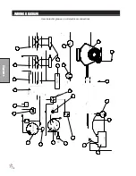
Page 12: ...10 Diagrams WIRING DIAGRAM Use dielectric grease on all electrical connections ...
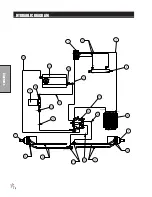
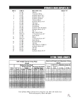
Page 14: ...12 Diagrams HYDRAULIC DIAGRAM ...
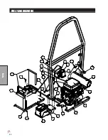
Page 16: ...14 Parts MAIN BODY DRAWING ...
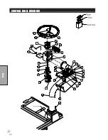
Page 18: ...16 Parts CONTROL PANEL DRAWING ...
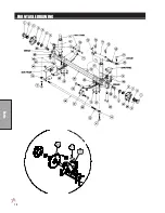
Page 20: ...18 Parts FRONT AXLE DRAWING ...
Page 22: ...20 Parts SEAT CONSOLE AND ROPS DRAWING ...
Page 24: ...22 Parts FUEL TANK DRAWING ...
Page 26: ...24 Parts OIL TANK OIL FILTER OIL COOLER DRAWING ...
Page 28: ...26 Parts FOOT PEDAL LINKAGE DRAWING ...
Page 30: ...28 Parts PUMP DRAWING ...
Page 32: ...30 Parts ENGINE AND SPRAY PUMP DRAWING ...
Page 34: ...32 Parts PARK BRAKE DRAWING ...
Page 36: ...34 Parts REAR AXLE DRAWING ...
Page 38: ...36 Parts TANK DRAWING TURBO QUAD AGITATOR DRAWING ...
Page 40: ...38 Parts 15 301 ORBITROL DRAWING ...
Page 42: ...40 Parts 45 373 DDC20 PISTON PUMP DRAWING ...
Page 53: ...51 Accessories NOTES ...
Page 54: ...52 Accessories 17 835 BOOM DRAWING ...
Page 65: ...63 Accessories NOTES ...
Page 68: ...66 Accessories 16 906 ELECTRIC HOSE REEL DRAWING ...
Page 70: ...68 Accessories 16 129 MANUAL HOSE REEL DRAWING ...
Page 80: ...78 Accessories FOAMER NOZZLE MOUNT HOSE GUARD MOUNT DRAWING ...
Page 82: ...80 Accessories 14 291 FOAMER REPLACEMENT PARTS ...
Page 88: ...86 Accessories 15 620 CHEMICAL CLEAN LOAD DRAWING ...


