5
Ser
vice
MAINTENANCE
ENGINE OIL
Change and add oil according to chart below. Do not overfill. Engine oil capacity is 2 quarts. We recommend
high-quality detergent oils classified for service SF, SG, SH, SJ or higher. Do not use special additives. Out
-
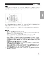
door temperatures determine the proper oil viscosity for the engine. Use the chart to select the best viscosity
for the outdoor temperature range expected
SAE VISCOSITY GRADES
Use of multi-viscosity oils (10W-30, etc.) above 80° F (27° C) will result in high oil consumption and possible
engine damage. Check oil level more frequently if using these types of oils.
SAE 30 oil, if used below 40° F (4° C), will result in hard starting and possible engine bore damage due to
inadequate lubrication.
HYDRAULIC OIL
1. Use SAE 10W-40 API Service SJ or higher motor oil.
2. For proper warranty, change oil every 500 hours or annually, which ever is first. Change the filter after
the first 50 hours, then every 250 hours thereafter.
3. Oil level should be 2-2½" (5-6.4cm) from top of the tank when fluid is cold. Do not overfill.
4. After changing oil, run the machine for a few minutes. Check oil level and for leaks.
5.
Always use extreme caution when filling hydraulic oil tank or checking level to keep system free of con
-
taminants.
Check and service more frequently when operating in extremely cold, hot or dusty conditions.
6. If the natural color of the fluid has become black or smells burnt, it is possible that an overheating prob
-
lem exists.
7. If fluid becomes milky, water contamination may be a problem.
8. If either of the above conditions happen, change oil immediately after fluid is cool and find the cause.
Take fluid level readings when the system is cold.
9. In extreme temperatures you can use straight weight oil. We recommend SAE 30W API Service SG
when hot (above 90°F (33°C)) and SAE 10W API Service SJ or higher when cold (below 32°F (0°C)
ambient temperature. Use either motor oil or hydraulic oil, but do not mix.
10. Oil being added to the system must be the same as what is already in the tank.
Mark the tank fill area
as to which type you put in.
Summary of Contents for 100684
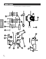
Page 12: ...10 Diagrams WIRING DIAGRAM Use dielectric grease on all electrical connections ...
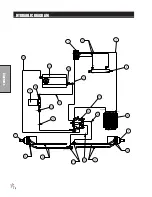
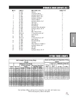
Page 14: ...12 Diagrams HYDRAULIC DIAGRAM ...
Page 16: ...14 Parts MAIN BODY DRAWING ...
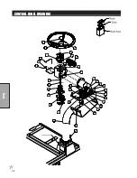
Page 18: ...16 Parts CONTROL PANEL DRAWING ...
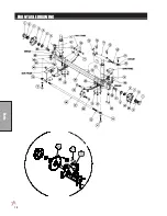
Page 20: ...18 Parts FRONT AXLE DRAWING ...
Page 22: ...20 Parts SEAT CONSOLE AND ROPS DRAWING ...
Page 24: ...22 Parts FUEL TANK DRAWING ...
Page 26: ...24 Parts OIL TANK OIL FILTER OIL COOLER DRAWING ...
Page 28: ...26 Parts FOOT PEDAL LINKAGE DRAWING ...
Page 30: ...28 Parts PUMP DRAWING ...
Page 32: ...30 Parts ENGINE AND SPRAY PUMP DRAWING ...
Page 34: ...32 Parts PARK BRAKE DRAWING ...
Page 36: ...34 Parts REAR AXLE DRAWING ...
Page 38: ...36 Parts TANK DRAWING TURBO QUAD AGITATOR DRAWING ...
Page 40: ...38 Parts 15 301 ORBITROL DRAWING ...
Page 42: ...40 Parts 45 373 DDC20 PISTON PUMP DRAWING ...
Page 53: ...51 Accessories NOTES ...
Page 54: ...52 Accessories 17 835 BOOM DRAWING ...
Page 65: ...63 Accessories NOTES ...
Page 68: ...66 Accessories 16 906 ELECTRIC HOSE REEL DRAWING ...
Page 70: ...68 Accessories 16 129 MANUAL HOSE REEL DRAWING ...
Page 80: ...78 Accessories FOAMER NOZZLE MOUNT HOSE GUARD MOUNT DRAWING ...
Page 82: ...80 Accessories 14 291 FOAMER REPLACEMENT PARTS ...
Page 88: ...86 Accessories 15 620 CHEMICAL CLEAN LOAD DRAWING ...


