75
Accessories
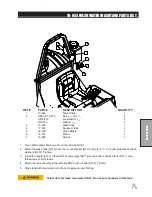
10-740 FOAM MARKER CONTROL PANEL
REF# PART#
DESCRIPTION
QUANTITY
1
10-739
Switch Mount Plate
1
15-725
Panel Mount End
2
2
15-782
Switch, Unlit
1
15-727
Rocker, No Light
1
3
15-918
Switch, 2 Red LED
1
15-917
Rocker, 2 Red Lenses
1
4
30-374
Decal, Foamer
1
Safety: Before working on machine stop engine, set park brake, remove
key from ignition and block wheels. Disconnect negative (-) battery termi-
nal.
1. Place decal(Ref 4) on Switch mount palte. Place panel mount ends in mount palte.
2. Mount switches (Ref 2 & 3) to switch mount plate (Ref 1)as shown above. Mount the switch mount
plate(Ref 1) on the side control panel using exixting bolts.
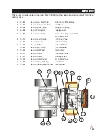
Tank Mount Drawing
3. Position the right and left hand mount brackets(Ref 2 and 4) on the boom tubes facing the front of the
machine, using two
5
/
16
x 3 bolts. Install the foamer plate (Ref 5) on the right and left bracket with curve
towards poly spray tank.
4. Place the piece of trim (Ref 13) on the foamer bracket to prevent rubbing of hoses for a cleanload sys
-
tem.
5. Place foamer unit onto mount plate, with cap facing to the right side of machine. Using ¼ bolts and
flange nuts, bolt foam marker to mount plate. The left rear mount of the foamer will bolt through the
mount plate and brace. Tighten all hardware.
6. Make sure all bolts are tightened.
Summary of Contents for 100684
Page 12: ...10 Diagrams WIRING DIAGRAM Use dielectric grease on all electrical connections ...
Page 14: ...12 Diagrams HYDRAULIC DIAGRAM ...
Page 16: ...14 Parts MAIN BODY DRAWING ...
Page 18: ...16 Parts CONTROL PANEL DRAWING ...
Page 20: ...18 Parts FRONT AXLE DRAWING ...
Page 22: ...20 Parts SEAT CONSOLE AND ROPS DRAWING ...
Page 24: ...22 Parts FUEL TANK DRAWING ...
Page 26: ...24 Parts OIL TANK OIL FILTER OIL COOLER DRAWING ...
Page 28: ...26 Parts FOOT PEDAL LINKAGE DRAWING ...
Page 30: ...28 Parts PUMP DRAWING ...
Page 32: ...30 Parts ENGINE AND SPRAY PUMP DRAWING ...
Page 34: ...32 Parts PARK BRAKE DRAWING ...
Page 36: ...34 Parts REAR AXLE DRAWING ...
Page 38: ...36 Parts TANK DRAWING TURBO QUAD AGITATOR DRAWING ...
Page 40: ...38 Parts 15 301 ORBITROL DRAWING ...
Page 42: ...40 Parts 45 373 DDC20 PISTON PUMP DRAWING ...
Page 53: ...51 Accessories NOTES ...
Page 54: ...52 Accessories 17 835 BOOM DRAWING ...
Page 65: ...63 Accessories NOTES ...
Page 68: ...66 Accessories 16 906 ELECTRIC HOSE REEL DRAWING ...
Page 70: ...68 Accessories 16 129 MANUAL HOSE REEL DRAWING ...
Page 80: ...78 Accessories FOAMER NOZZLE MOUNT HOSE GUARD MOUNT DRAWING ...
Page 82: ...80 Accessories 14 291 FOAMER REPLACEMENT PARTS ...
Page 88: ...86 Accessories 15 620 CHEMICAL CLEAN LOAD DRAWING ...


