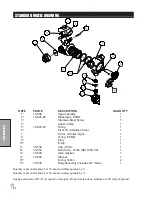
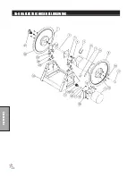
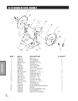

96
Accessories
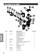
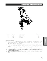
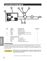
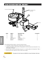
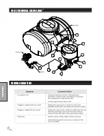
ELECTRIC HOSE REEL WIRING DIAGRAM
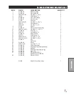
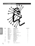
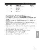
REF# PART#
DESCRIPTION
QUANTITY
8843-132
Flex guard
3
/
8
ID
1
1
8919-144
10GA Red Wire 144"
1
8901
Slide-On Connector
1
2
16-979
Wire, Switch to Solenoid Hot Terminal
1
3
33-251
Push Button Switch
1
4
16-978
Wire, Switch to Solenoid Start Terminal
1
6
12-015
Solenoid
1
SOLENOID TERMINALS
HN -516-24
5
/
16
- 24 Hex Nut
2
HN -10-32
10 - 32 Hex Nut
1
7
8931-144
10GA White Wire 144"
1
8901
Slide-On Connector
1
8
33-273
Auto Blade Type Fuse 30Amp
1
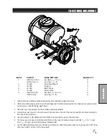
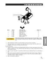
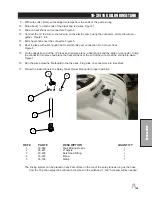
CONNECTION INSTRUCTIONS
Route wire harness along side of tank and over to fuse block taking care to stay clear of moving parts or hot
engine components. Cut off excess wire and strip back
3
/
8
". Place one 8963 heat shrink (
1
/
4
x 1
1
/
4
) on each
wire before crimping 8901 slide on connectors to the red and white wires. Connect the two wires to the fuse
block first the red to the (+) positive and the white to the (-) negative. Put the 33-273 auto blade type fuse (30
amp) into fuse block.
Make certain you are connecting positive (+) to positive; negative (-) to nega-
tive while attaching power leads. If you do not observe polarity, damage will
result to electrical components.
Use Dielectric Grease On All Electrical Connections
Summary of Contents for 10-100-F
Page 12: ...10 Diagrams WIRING DIAGRAM Use dielectric grease on all electrical connections ...
Page 14: ...12 Diagrams HYDRAULIC DIAGRAM ...
Page 16: ...14 Parts MAIN BODY DRAWING ...
Page 18: ...16 Parts CONTROL PANEL DRAWING ...
Page 20: ...18 Parts FRONT AXLE DRAWING ...
Page 22: ...20 Parts SEAT CONSOLE DRAWING ...
Page 24: ...22 Parts FUEL TANK DRAWING ...
Page 26: ...24 Parts OIL TANK OIL FILTER OIL COOLER DRAWING ...
Page 28: ...26 Parts FOOT PEDAL LINKAGE DRAWING ...
Page 30: ...28 Parts PUMP DRAWING ...
Page 32: ...30 Parts ENGINE AND SPRAY PUMP DRAWING ...
Page 34: ...32 Parts PARK BRAKE DRAWING ...
Page 36: ...34 Parts REAR AXLE DRAWING ...
Page 38: ...36 Parts TANK DRAWING TURBO QUAD AGITATOR DRAWING ...
Page 40: ...38 Parts 15 301 ORBITAL DRAWING ...
Page 42: ...40 Parts 45 373 DDC20 PISTON PUMP DRAWING ...
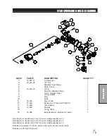
Page 54: ...52 Accessories CONTROL MOUNTS ...
Page 61: ...59 Accessories STAR COMMAND I WIRING 10 716 M ...
Page 66: ...64 Accessories 10 648 3 WAY MANUAL VALVE DRAWING ...
Page 71: ...69 Accessories NOTES ...
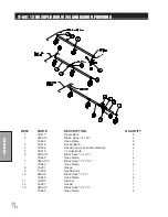
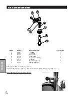
Page 72: ...70 Accessories 17 585 18 HD BOOM DRAWING ...
Page 74: ...72 Accessories 17 585 18 HD BOOM DRAWING ...
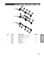
Page 80: ...78 Accessories 17 601 15 HD BOOM DRAWING ...
Page 82: ...80 Accessories 17 601 15 HD BOOM DRAWING ...
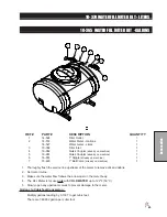
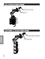
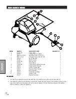
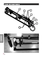
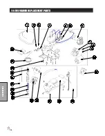
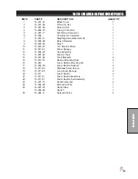
Page 92: ...90 Accessories 16 906 ELECTRIC HOSE REEL DRAWING ...
Page 104: ...102 Accessories FOAMER NOZZLE MOUNT DRAWING ...
Page 106: ...104 Accessories 14 291 FOAMER REPLACEMENT PARTS ...
Page 112: ...110 Accessories 10 417 CHEMICAL CLEAN LOAD TROUBLE SHOOTING ...
Page 114: ...112 Accessories 15 620 CHEMICAL CLEAN LOAD DRAWING ...