93
Accessories
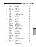
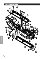
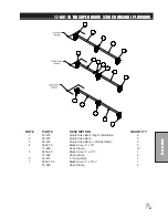
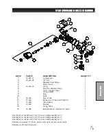
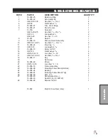
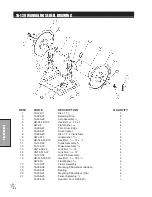
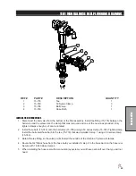
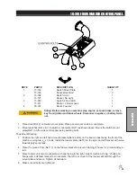
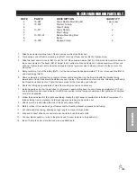
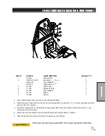
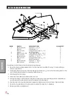
10-422 HOSE REEL MOUNT
REF# PART#
DESCRIPTION
QUANTITY
1
HB-516-18-150
Hex Bolt,
5
/
16
- 18 x 1
1
/
2
4
HNTL-516-18
Lock Nut,
5
/
16
- 18
4
2
10-423
Hose Reel Mount
1
3
10-559
Support
2
4
18-249
Barb Fitting
1
5
16-295
Hose Fitting
1
6
HB-38-16-350
Hex Bolt,
3
/
8
- 16 x 3
1
/
2
4
HNTL-38-16
Lock Nut,
3
/
8
- 16
4
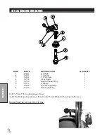
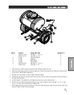
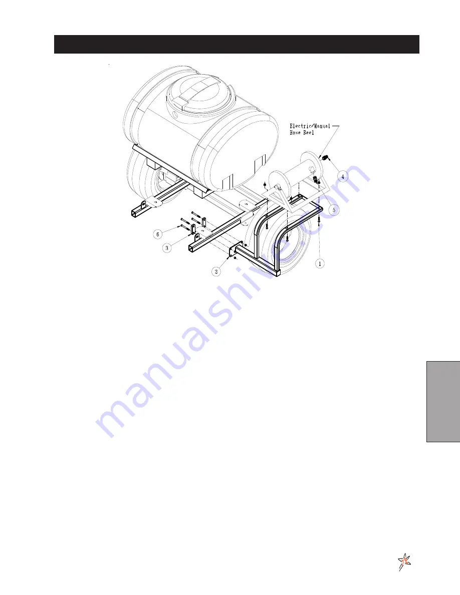
1. Wear protective clothing when draining the tank and taking apart the lines.
2. Drain tank and spray system in a safe and approved method insuring that no chemical or water remain
in tank as you will be taking apart lines.
3. Remove key from ignition, set park brake and block wheels.
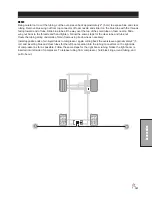
4. Install hose reel mount on the left side of the machine in front of the rear wheel. Mount arms pointing to
the rear of the machine.
5. Use the four(4)
3
/
8
Hex Bolts and Lock Nuts to secure the mount to the machine.
6. Put hose reel on hose reel bracket with fitting to the rear of machine. Use four bolts
5
/
16
- 18 x 1
1
/
2
and
four
5
/
16
- 18 lock nuts to hold in place. Tighten bolts.
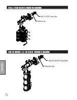
7. Put 18-249 barb fitting into side of hose reel. Place 16-295 Fitting into center of hose reel. Run 55" hose
from the 18-249 to the 15-749 hose barb.
Summary of Contents for 10-100-F
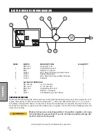
Page 12: ...10 Diagrams WIRING DIAGRAM Use dielectric grease on all electrical connections ...
Page 14: ...12 Diagrams HYDRAULIC DIAGRAM ...
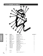
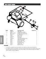
Page 16: ...14 Parts MAIN BODY DRAWING ...
Page 18: ...16 Parts CONTROL PANEL DRAWING ...
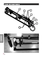
Page 20: ...18 Parts FRONT AXLE DRAWING ...
Page 22: ...20 Parts SEAT CONSOLE DRAWING ...
Page 24: ...22 Parts FUEL TANK DRAWING ...
Page 26: ...24 Parts OIL TANK OIL FILTER OIL COOLER DRAWING ...
Page 28: ...26 Parts FOOT PEDAL LINKAGE DRAWING ...
Page 30: ...28 Parts PUMP DRAWING ...
Page 32: ...30 Parts ENGINE AND SPRAY PUMP DRAWING ...
Page 34: ...32 Parts PARK BRAKE DRAWING ...
Page 36: ...34 Parts REAR AXLE DRAWING ...
Page 38: ...36 Parts TANK DRAWING TURBO QUAD AGITATOR DRAWING ...
Page 40: ...38 Parts 15 301 ORBITAL DRAWING ...
Page 42: ...40 Parts 45 373 DDC20 PISTON PUMP DRAWING ...
Page 54: ...52 Accessories CONTROL MOUNTS ...
Page 61: ...59 Accessories STAR COMMAND I WIRING 10 716 M ...
Page 66: ...64 Accessories 10 648 3 WAY MANUAL VALVE DRAWING ...
Page 71: ...69 Accessories NOTES ...
Page 72: ...70 Accessories 17 585 18 HD BOOM DRAWING ...
Page 74: ...72 Accessories 17 585 18 HD BOOM DRAWING ...
Page 80: ...78 Accessories 17 601 15 HD BOOM DRAWING ...
Page 82: ...80 Accessories 17 601 15 HD BOOM DRAWING ...
Page 92: ...90 Accessories 16 906 ELECTRIC HOSE REEL DRAWING ...
Page 104: ...102 Accessories FOAMER NOZZLE MOUNT DRAWING ...
Page 106: ...104 Accessories 14 291 FOAMER REPLACEMENT PARTS ...
Page 112: ...110 Accessories 10 417 CHEMICAL CLEAN LOAD TROUBLE SHOOTING ...
Page 114: ...112 Accessories 15 620 CHEMICAL CLEAN LOAD DRAWING ...