

1
Introduction
INTRODUCTION
Thank you for purchasing a
Smithco
product.
Read this manual and all other manuals pertaining to the Spray Star 1110 carefully as they contain safety, op
-
erating, assembly and maintenance instructions. Failure to do so could result in personal injury or equipment
damage.
Keep manuals in a safe place after operator and maintenance personnel have read them. Right and left sides
are from the operator’s seat, facing forward.
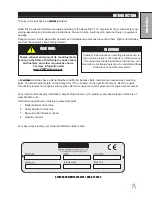
All
Smithco
machines have a Serial Number and Model Number. Both numbers are needed when ordering
parts. The serial number plate on the Spray Star 1110 is located on the right front bumper. Refer to engine
manual for placement of engine serial number. Refer to engine manual for placement of engine serial number.
For product and accessory information, help finding a dealer, or to register your product please contact us at
www.Smithco.com.
Information needed when ordering replacement parts:
1. Model Number of machine
2. Serial Number of machine
3. Name and Part Number of part
4. Quantity of parts
For easy access record your Serial and Model numbers here.
SMITHCO CUSTOMER SERVICE 1-800-891-9435
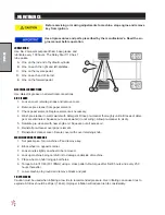
WARNING
Failure to follow cautious operating practices can re-
sult in serious injury to the operator or other persons.
The owner must understand these instructions, and
must allow only trained persons who understand these
instructions to operate this vehicle.
WARNING:
Engine exhaust and some of its constituents are
known to the State of California to cause cancer,
birth defects, and other reproductive harm.
For more information visit
www.P65Warning.ca.gov
Summary of Contents for 10-100-F
Page 12: ...10 Diagrams WIRING DIAGRAM Use dielectric grease on all electrical connections ...
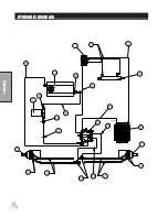
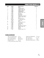
Page 14: ...12 Diagrams HYDRAULIC DIAGRAM ...
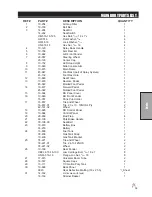
Page 16: ...14 Parts MAIN BODY DRAWING ...
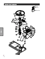
Page 18: ...16 Parts CONTROL PANEL DRAWING ...
Page 20: ...18 Parts FRONT AXLE DRAWING ...
Page 22: ...20 Parts SEAT CONSOLE DRAWING ...
Page 24: ...22 Parts FUEL TANK DRAWING ...
Page 26: ...24 Parts OIL TANK OIL FILTER OIL COOLER DRAWING ...
Page 28: ...26 Parts FOOT PEDAL LINKAGE DRAWING ...
Page 30: ...28 Parts PUMP DRAWING ...
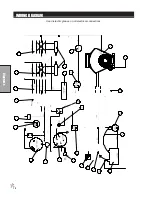
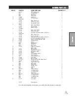
Page 32: ...30 Parts ENGINE AND SPRAY PUMP DRAWING ...
Page 34: ...32 Parts PARK BRAKE DRAWING ...
Page 36: ...34 Parts REAR AXLE DRAWING ...
Page 38: ...36 Parts TANK DRAWING TURBO QUAD AGITATOR DRAWING ...
Page 40: ...38 Parts 15 301 ORBITAL DRAWING ...
Page 42: ...40 Parts 45 373 DDC20 PISTON PUMP DRAWING ...
Page 54: ...52 Accessories CONTROL MOUNTS ...
Page 61: ...59 Accessories STAR COMMAND I WIRING 10 716 M ...
Page 66: ...64 Accessories 10 648 3 WAY MANUAL VALVE DRAWING ...
Page 71: ...69 Accessories NOTES ...
Page 72: ...70 Accessories 17 585 18 HD BOOM DRAWING ...
Page 74: ...72 Accessories 17 585 18 HD BOOM DRAWING ...
Page 80: ...78 Accessories 17 601 15 HD BOOM DRAWING ...
Page 82: ...80 Accessories 17 601 15 HD BOOM DRAWING ...
Page 92: ...90 Accessories 16 906 ELECTRIC HOSE REEL DRAWING ...
Page 104: ...102 Accessories FOAMER NOZZLE MOUNT DRAWING ...
Page 106: ...104 Accessories 14 291 FOAMER REPLACEMENT PARTS ...
Page 112: ...110 Accessories 10 417 CHEMICAL CLEAN LOAD TROUBLE SHOOTING ...
Page 114: ...112 Accessories 15 620 CHEMICAL CLEAN LOAD DRAWING ...