

111
Accessories
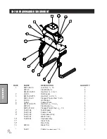
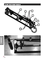
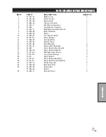
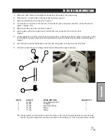
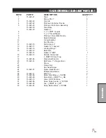
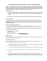
10-417 CHEMICAL CLEAN-LOAD
®
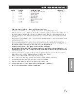
PART LIST
REF#
PART #
DESCRIPTION
QUANTITY
3
HBFL-516-18-075
Flange Bolt,
5
/
16
-18 x
3
/
4
4
HNFL-516-18
Flange Whiz-loc Nut,
5
/
16
-18
4
4
15-620
Clean-load Eductor
1
5
18-116
Hose Clamps
4
6
16-156
90° Hose Barb
3
7
18-391
Reducer Coupling
1
8
16-972
Elbow
1
9
8897-83
Hose to Tee by Valve
1
10
8897-41
Hose to fitting on Back of Tank
1
11
16-159
Tank Fitting
1
12
17-635
Mount Bracket
PART OF BOOM
1
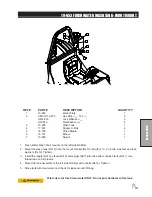
1. Make sure all chemicals have been flushed out of spray system, as you will be disconnecting fittings
from the pump. Remember to use threaded tape on all new fitting connections.
2. Remove the 1
1
/
4
" plug from the tee on the outlet side of the pump and install one Hose barb (16-156).
Then tighten so it points to the left side of the machine.
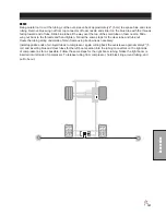
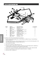
3. Install mounting brackets onto left side of center boom between boom pivot and vertical boom support.
Secure with
3
/
8
x 3 bolt, flat washer (top and bottom) and lock nut.
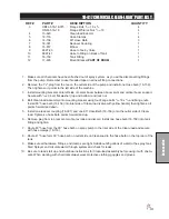
4. Bolt Clean-load assembly onto mounting bracket using four flange bolts
5
/
16
-18 x
3
/
4
and flange nuts.
Install 90° hose barb (16-156) into inlet side of Clean-load (valve with yellow handle) then tighten so it
points forward and down.
5. Install one reducer coupling (18-391) and one 90° Hose Barb (16-156) onto the outlet side of Clean-
load. Tighten so hose barb points forward and up.
6. Remove plug from top rear center of spray tank and discard. Install one hose barb (16-159) into tank
fitting and tighten.
7. Route 80" hose from the 90° hose barb on spray pump to the inlet side of the Clean-load and secure
with hose clamps (18-116).
8. Route 41" hose form 90° hose barb on outlet side on Clean-load to the hose barb on the top rear of the
tank.
9. Make sure all hardware, fittings, and clamps are tight. Add about 25 gallons of water to the spray tank.
Start Sprayer and circulate water through system and check for leaks.
10. Be sure to read start up and shutdown instructions for Clean-load assembly before using it with chemi
-
cals. When working with chemicals always wear protective clothing, goggles and gloves.
Summary of Contents for 10-100-F
Page 12: ...10 Diagrams WIRING DIAGRAM Use dielectric grease on all electrical connections ...
Page 14: ...12 Diagrams HYDRAULIC DIAGRAM ...
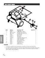
Page 16: ...14 Parts MAIN BODY DRAWING ...
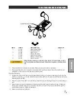
Page 18: ...16 Parts CONTROL PANEL DRAWING ...
Page 20: ...18 Parts FRONT AXLE DRAWING ...
Page 22: ...20 Parts SEAT CONSOLE DRAWING ...
Page 24: ...22 Parts FUEL TANK DRAWING ...
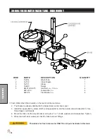
Page 26: ...24 Parts OIL TANK OIL FILTER OIL COOLER DRAWING ...
Page 28: ...26 Parts FOOT PEDAL LINKAGE DRAWING ...
Page 30: ...28 Parts PUMP DRAWING ...
Page 32: ...30 Parts ENGINE AND SPRAY PUMP DRAWING ...
Page 34: ...32 Parts PARK BRAKE DRAWING ...
Page 36: ...34 Parts REAR AXLE DRAWING ...
Page 38: ...36 Parts TANK DRAWING TURBO QUAD AGITATOR DRAWING ...
Page 40: ...38 Parts 15 301 ORBITAL DRAWING ...
Page 42: ...40 Parts 45 373 DDC20 PISTON PUMP DRAWING ...
Page 54: ...52 Accessories CONTROL MOUNTS ...
Page 61: ...59 Accessories STAR COMMAND I WIRING 10 716 M ...
Page 66: ...64 Accessories 10 648 3 WAY MANUAL VALVE DRAWING ...
Page 71: ...69 Accessories NOTES ...
Page 72: ...70 Accessories 17 585 18 HD BOOM DRAWING ...
Page 74: ...72 Accessories 17 585 18 HD BOOM DRAWING ...
Page 80: ...78 Accessories 17 601 15 HD BOOM DRAWING ...
Page 82: ...80 Accessories 17 601 15 HD BOOM DRAWING ...
Page 92: ...90 Accessories 16 906 ELECTRIC HOSE REEL DRAWING ...
Page 104: ...102 Accessories FOAMER NOZZLE MOUNT DRAWING ...
Page 106: ...104 Accessories 14 291 FOAMER REPLACEMENT PARTS ...
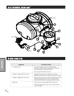
Page 112: ...110 Accessories 10 417 CHEMICAL CLEAN LOAD TROUBLE SHOOTING ...
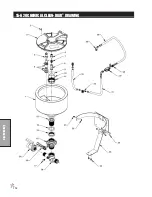
Page 114: ...112 Accessories 15 620 CHEMICAL CLEAN LOAD DRAWING ...