


55
Accessories
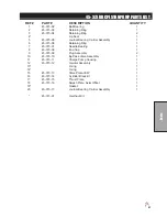
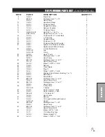
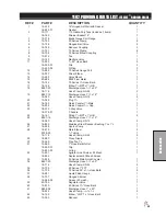
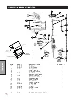
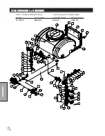
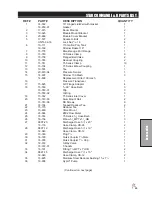
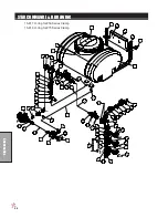
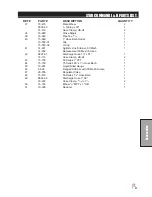
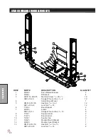
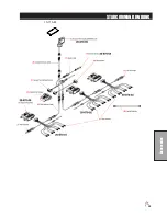
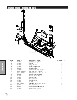
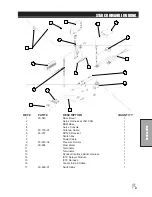
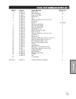
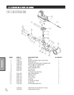
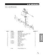
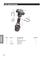
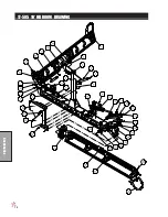
STAR COMMAND I & II PARTS LIST
REF# PART#
DESCRIPTION
QUANTITY
1
14-532
16" Hinged Lid/Well with Gasket
1
16-953-01
Gasket
1
2
17-615
Boom Mounts
2
3
10-625
Module Mount Bracket
1
4
20-666
Module Cover Bracket
1
5
17-537
Square U-Bolt
2
HNTL-38-16
Lock Nut,
3
/
8
- 16
4
6
10-111
110 Gallon Poly Tank
1
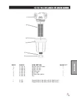
16-169
Strainer Basket 16"
1
7
15-778
Blank Gauge Port Flange
1
8
15-740
50 Series Clamp
9
9
15-738
Flanged Ball Valve
2
10
15-748
Reducer Coupling
2
11
15-741
75 Series Clamp
10
12
15-734
75 Series Elbow Coupling
1
13
10-574
Tee
1
14
20-670-04
Pressure Sensor
1
15
14-607
Strainer 100 Mesh
3
14-609
Replacement Filter 100 mesh
16
Pressure Transducer
1
17
15-825
QC Flange Adapter
4
18
15-553
3
/
4
-90° Hose Barb
3
15-553-01
Clip
3
15-553-02
O-Ring
3
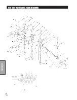
19
15-742
75 Series Inlet Cover
1
20
15-743-03
Alum Mount Rail
2
15-743-06
SS Screws
8
21
30-164
Tapped Reducer Tee
2
22
15-775
Reducer Tee
1
23
10-480
Valve Mount
1
24
20-684
#802 Flow Meter
1
25
15-744
75 Series 1
1
/
4
Hose Barb
1
26
16-156
Elbow 1
1
/
4
MPT x1
1
/
4
HB
3
27
8897-23
Discharge Hose 1
1
/
4
" x 23"
1
18-116
Hose Clamp, HS-24
2
28
8897-19
Discharge Hose 1
1
/
4
" x 19"
1
18-040
Hose Clamp, HS-12
2
29
10-389
Plug 1
1
/
4
1
30
16-180
Quick Coupler 1
1
/
4
Male
1
31
16-935
Quick Coupler 1
1
/
4
Cap
1
32
18-372
3-Way Valve
1
18-372-01
T-handle
1
33
16-161
Fitting 1
1
/
4
MPT x 1
1
/
4
HB 2
34
8897-15
Discharge Hose 1
1
/
4
" x 15"
1
18-040
Hose Clamp, HS-12
2
35
16-825
Stainless Steel Reducer Bushing 1
1
/
2
x 1
1
/
4
1
36
16-998
Hypro
®
Pump
1
(Continued on next page)
Summary of Contents for 10-100-F
Page 12: ...10 Diagrams WIRING DIAGRAM Use dielectric grease on all electrical connections ...
Page 14: ...12 Diagrams HYDRAULIC DIAGRAM ...
Page 16: ...14 Parts MAIN BODY DRAWING ...
Page 18: ...16 Parts CONTROL PANEL DRAWING ...
Page 20: ...18 Parts FRONT AXLE DRAWING ...
Page 22: ...20 Parts SEAT CONSOLE DRAWING ...
Page 24: ...22 Parts FUEL TANK DRAWING ...
Page 26: ...24 Parts OIL TANK OIL FILTER OIL COOLER DRAWING ...
Page 28: ...26 Parts FOOT PEDAL LINKAGE DRAWING ...
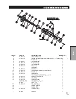
Page 30: ...28 Parts PUMP DRAWING ...
Page 32: ...30 Parts ENGINE AND SPRAY PUMP DRAWING ...
Page 34: ...32 Parts PARK BRAKE DRAWING ...
Page 36: ...34 Parts REAR AXLE DRAWING ...
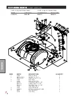
Page 38: ...36 Parts TANK DRAWING TURBO QUAD AGITATOR DRAWING ...
Page 40: ...38 Parts 15 301 ORBITAL DRAWING ...
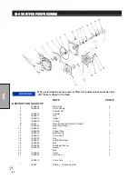
Page 42: ...40 Parts 45 373 DDC20 PISTON PUMP DRAWING ...
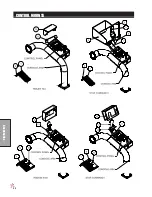
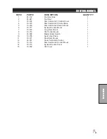
Page 54: ...52 Accessories CONTROL MOUNTS ...
Page 61: ...59 Accessories STAR COMMAND I WIRING 10 716 M ...
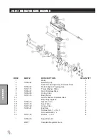
Page 66: ...64 Accessories 10 648 3 WAY MANUAL VALVE DRAWING ...
Page 71: ...69 Accessories NOTES ...
Page 72: ...70 Accessories 17 585 18 HD BOOM DRAWING ...
Page 74: ...72 Accessories 17 585 18 HD BOOM DRAWING ...
Page 80: ...78 Accessories 17 601 15 HD BOOM DRAWING ...
Page 82: ...80 Accessories 17 601 15 HD BOOM DRAWING ...
Page 92: ...90 Accessories 16 906 ELECTRIC HOSE REEL DRAWING ...
Page 104: ...102 Accessories FOAMER NOZZLE MOUNT DRAWING ...
Page 106: ...104 Accessories 14 291 FOAMER REPLACEMENT PARTS ...
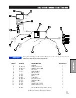
Page 112: ...110 Accessories 10 417 CHEMICAL CLEAN LOAD TROUBLE SHOOTING ...
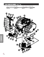
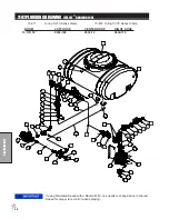
Page 114: ...112 Accessories 15 620 CHEMICAL CLEAN LOAD DRAWING ...