95
Accessories
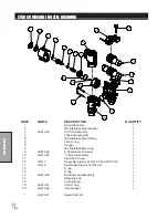
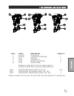
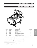
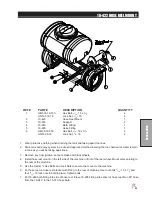
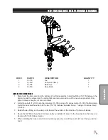
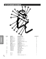
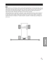
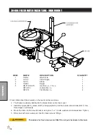
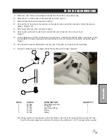
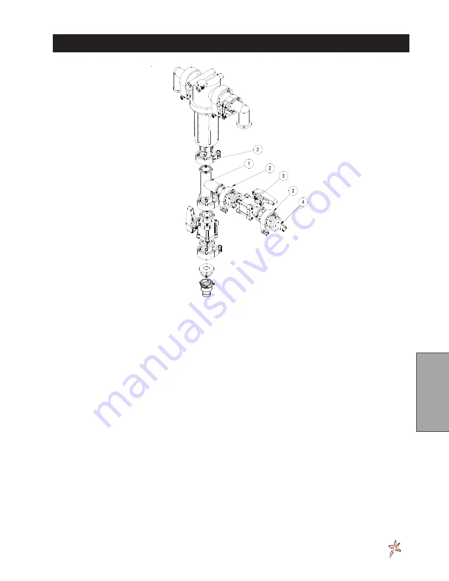
1101 MANUAL HOSE REEL PLUMBING DRAWING
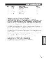
REF# PART#
DESCRIPTION
QUANTITY
1
15-776
Tee
1
2
15-740
50 Series Clamp
3
3
15-738
Ball Valve
1
4
15-749
Hose Barb
1
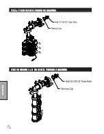
INSTALLATION INSTRUCTIONS
1. Disconnect the ball valve from the bottom of the filter assembly. Install tee fitting (15-776) between the
ball valve and the elbow. Use the clamp that was removed and one of the new ones provided. Only
tighten clamps enough so it can be rotated.
2. Install hose barb (15-749) onto the ball valve (15-738) using a 50 series clamp (15-740) Tighten clamp.
Install the ball valve/hose barb to the tee (15-776) that was installed in step 1 using a 50 series clamp
(15-740).
3. Rotate the tee fitting so the valve points toward the outside of the machine. Tighten all clamps.
4. Route the 3/4" Black hose from the hose barb you installed in step 2 to the hose barb on the hose reel.
Secure with 18-040 Hose clamps.
5. When installing the hose reel with a manual spray system you will have parts left over that you will not
need.
Summary of Contents for 10-100-F
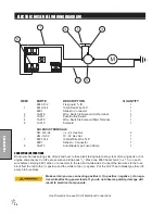
Page 12: ...10 Diagrams WIRING DIAGRAM Use dielectric grease on all electrical connections ...
Page 14: ...12 Diagrams HYDRAULIC DIAGRAM ...
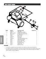
Page 16: ...14 Parts MAIN BODY DRAWING ...
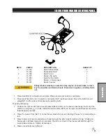
Page 18: ...16 Parts CONTROL PANEL DRAWING ...
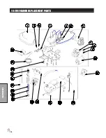
Page 20: ...18 Parts FRONT AXLE DRAWING ...
Page 22: ...20 Parts SEAT CONSOLE DRAWING ...
Page 24: ...22 Parts FUEL TANK DRAWING ...
Page 26: ...24 Parts OIL TANK OIL FILTER OIL COOLER DRAWING ...
Page 28: ...26 Parts FOOT PEDAL LINKAGE DRAWING ...
Page 30: ...28 Parts PUMP DRAWING ...
Page 32: ...30 Parts ENGINE AND SPRAY PUMP DRAWING ...
Page 34: ...32 Parts PARK BRAKE DRAWING ...
Page 36: ...34 Parts REAR AXLE DRAWING ...
Page 38: ...36 Parts TANK DRAWING TURBO QUAD AGITATOR DRAWING ...
Page 40: ...38 Parts 15 301 ORBITAL DRAWING ...
Page 42: ...40 Parts 45 373 DDC20 PISTON PUMP DRAWING ...
Page 54: ...52 Accessories CONTROL MOUNTS ...
Page 61: ...59 Accessories STAR COMMAND I WIRING 10 716 M ...
Page 66: ...64 Accessories 10 648 3 WAY MANUAL VALVE DRAWING ...
Page 71: ...69 Accessories NOTES ...
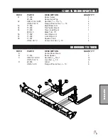
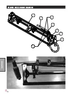
Page 72: ...70 Accessories 17 585 18 HD BOOM DRAWING ...
Page 74: ...72 Accessories 17 585 18 HD BOOM DRAWING ...
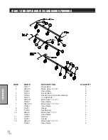
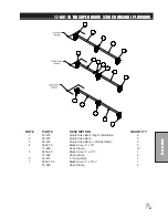
Page 80: ...78 Accessories 17 601 15 HD BOOM DRAWING ...
Page 82: ...80 Accessories 17 601 15 HD BOOM DRAWING ...
Page 92: ...90 Accessories 16 906 ELECTRIC HOSE REEL DRAWING ...
Page 104: ...102 Accessories FOAMER NOZZLE MOUNT DRAWING ...
Page 106: ...104 Accessories 14 291 FOAMER REPLACEMENT PARTS ...
Page 112: ...110 Accessories 10 417 CHEMICAL CLEAN LOAD TROUBLE SHOOTING ...
Page 114: ...112 Accessories 15 620 CHEMICAL CLEAN LOAD DRAWING ...