50
COMX-CORE-2610-ET Installation and Use (6806800P11E)
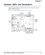
Controls, LEDs, and Connectors
Onboard LEDs
3.2
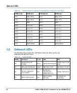
Onboard LEDs
The following table provides the information about the LEDs used by the
COMX-CORE-2610-ET board.
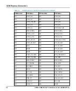
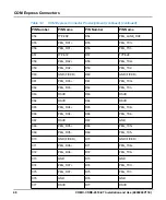
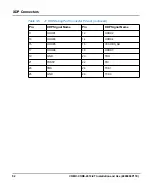
C101
P
D101
P
C102
PEG_RX15-
D102
PEG_TX15-
C103
GND
D103
GND
C104
VCC_12V
D104
VCC_12V
C105
VCC_12V
D105
VCC_12V
C106
VCC_12V
D106
VCC_12V
C107
VCC_12V
D107
VCC_12V
C108
VCC_12V
D108
VCC_12V
C109
VCC_12V
D109
VCC_12V
C110
GND (FIXED)
D110
GND (FIXED)
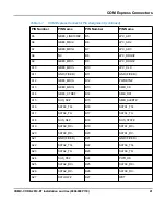
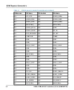
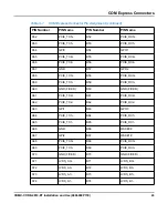
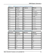
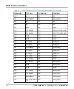
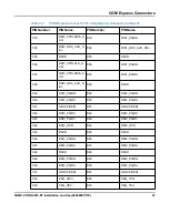
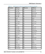
Table 3-2
COM Express Connector Pin Assignment (continued) (continued)
PIN Number
PIN Name
PIN Number
PIN Name
Table 3-3
Onboard LEDs
RefDes
Function
Color
ON
OFF
D6
System Power OK
Indicator
Green
System Power is good.
System Power is not
good.
D5
PM Power OK Indicator
Green
PM Power is OK.
PM Power is not OK.
D4
System Catastrophic
error Indicator
Red
System has
experienced a
catastrophic error.
System has No error.
D3
PROCHOT# Indicator
Red
PROCHOT# is
asserted.
PROCHOT# is
deasserted.
Summary of Contents for COMX-CORE-2610-ET
Page 1: ...COMX CORE 2610 ET Installation and Use P N 6806800P11E January 2020...
Page 6: ...6 COMX CORE 2610 ET Installation and Use 6806800P11E Table of Contents...
Page 8: ...List of Figures 8 COMX CORE 2610 ET Installation and Use 6806800P11E...
Page 16: ...16 COMX CORE 2610 ET Installation and Use 6806800P11E About this Manual...
Page 88: ...88 COMX CORE 2610 ET Installation and Use 6806800P11E BIOS Standard Status Codes...
Page 91: ...1...

