40
COMX-CORE-2610-ET Installation and Use (6806800P11E)
Controls, LEDs, and Connectors
Connectors and Switches
3.1
Connectors and Switches
3.1.1
COM Express Connectors
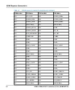
COMX-CORE-2610-ET supports Type 6 COM Express connector definition. The signals
from COM Express connector are based COM-E SPEC2.0 standard. This section
describes the COM Express connector used on the board. The following table lists the
signals definitions.
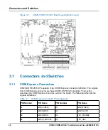
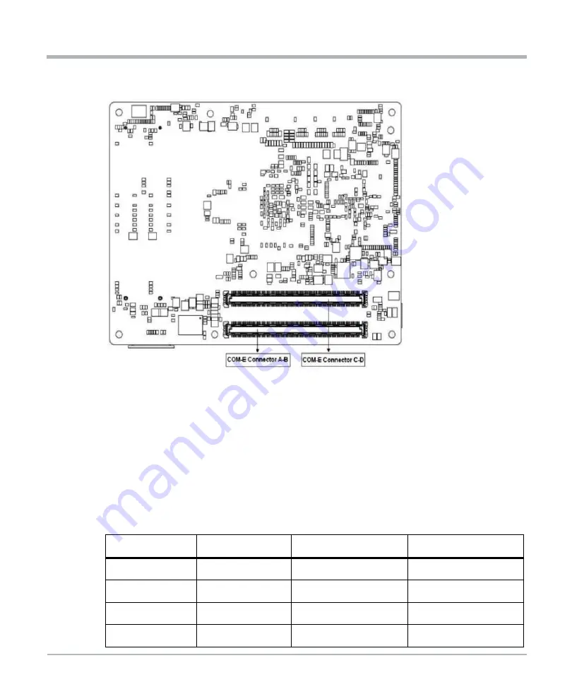
Figure 3-2
COMX-CORE-2610-ET Board Layout (Bottom view)
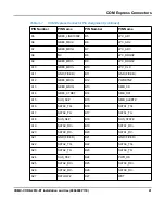
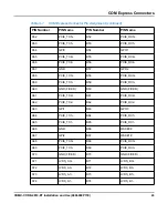
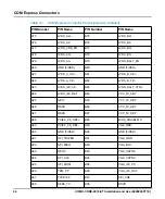
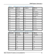
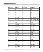
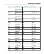
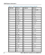
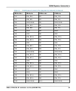
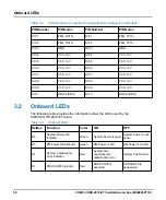
Table 3-1
COM Express Connector Pin Assignment
PIN Number
PIN Name
PIN Number
PIN Name
A1
GND (FIXED)
B1
GND (FIXED)
A2
GBE0_MDI3-
B2
GBE0_ACT#
A3
GB
B3
LPC_FRAME#
A4
GBE0_LINK100#
B4
LPC_AD0
Summary of Contents for COMX-CORE-2610-ET
Page 1: ...COMX CORE 2610 ET Installation and Use P N 6806800P11E January 2020...
Page 6: ...6 COMX CORE 2610 ET Installation and Use 6806800P11E Table of Contents...
Page 8: ...List of Figures 8 COMX CORE 2610 ET Installation and Use 6806800P11E...
Page 16: ...16 COMX CORE 2610 ET Installation and Use 6806800P11E About this Manual...
Page 88: ...88 COMX CORE 2610 ET Installation and Use 6806800P11E BIOS Standard Status Codes...
Page 91: ...1...

