background image

4K-866 USER MANUAL V1.0


© 2018 Smart-e (UK) Ltd 

www.smart-e.co.uk 

PAGE | 3 


WARNING 


In  order  to ensure  the  reliable performance  of  the equipment and  the safety  of  the  user,  please  observe  the  following 
matters during the process of installation, use and maintenance. : 

INSTALLATION 


Please do not use this product in the following places: places with high levels of dust or soot; places with high electric 
conductivity; places with corrosive or combustible gas; places exposed to high temperature, condensation, wind or 
rain; places subject to the occasion of vibration or impact.  


When installing screw or wiring, make sure that metal scraps and wire heads will not fall into the screw shaft of the 
equipment, as it could cause a fire, fault, or incorrect operation. 


When the installation work is completed, ensure there is nothing left on the ventilated vents of the equipment, including 
packaging items. Blocked vents may cause a fire, fault, incorrect operation. 


Avoid wiring and inserting cable plugs in a charged state, otherwise it is easy to cause shock, or electrical damage. 


The installation wiring should be strong reliable and earthed. 


For installations in areas of high interference, the installer should choose shielded cable as the high frequency signal 
input or output cable, so as to improve the anti-interference ability of the system. 


Switch off and disconnect the equipment from all power sources prior to handling, installation or wiring, otherwise it 
may cause electric shock or equipment damage. 


This product grounds to earth by the grounding wires. To avoid electric shocks, grounding wires and the earth must 
be linked together. Before the connection of input or output terminals, please make sure this product is correctly 
grounded. 


All terminals and wiring should be fully sheathed or otherwise covered before connecting the equipment to a power 
supply so as to avoid cause electric shock. 


OPERATION AND MAINTENANCE 


Be sure to read this manual, and fully comply with the safety recommendations, before undertaking maintenance or 
operation. 


Do not touch terminals whilst the equipment is in a powered state, or it may cause a shock, incorrect operation. 


Switch  off  and  disconnect  the  equipment  from  all  power  sources  prior  to  cleaning  or  tightening  terminals  or 
connections. These operations can lead to electric shock in a live current state. 


Switch  off  and  disconnect  the  equipment  from  all  power  sources  prior  to  the  connection  or  disconnection  of 
communication  signal  cables,  expansion  modules,  or  other  adapters,  or  it  may  cause  damage  to  the  equipment, 
incorrect operation, or lead to electric shock in a live current state. 


Do not dismantle the equipment and avoid damaging the internal electrical components. Please refer all servicing to 
qualified service personnel. 


DISPOSAL 


Be sure to dispose of the equipment in accordance with local regulations. 


Summary of Contents for 4K-866

Page 1: ......

Page 2: ...ich may cause or be susceptible to radio interference Users may need to take additional measures to mitigate the interference This is an RF Radio product which may cause or be susceptible to radio int...

Page 3: ...stem Switch off and disconnect the equipment from all power sources prior to handling installation or wiring otherwise it may cause electric shock or equipment damage This product grounds to earth by...

Page 4: ...DIAGRAM 9 5 WHAT IS INCLUDED 10 6 ACCESSORIES 11 6 1 INFRA RED RECEIVERS IR RX 11 6 2 INFRA RED TRANSMITTERS IR TX 12 6 3 RS232 PLUGS 13 6 4 POWER SUPPLY AND MAINS ADAPTER PLUG 14 7 BASIC SETUP 15 8...

Page 5: ...on the power supply could be attached to the transmitter in your AV source cupboard and power supplied remotely to the receiver at the screen location The 4K 866 also offers the ability to extend ethe...

Page 6: ...pport HDMI up to 340MHz TMDS clock HDCP EDID DCC transparent link HDMI resolutions 4K 2K 1080p HDCP 2 2 compatible Full duplex RS232 passthrough Bi directional infra red passthrough 100BaseT Ethernet...

Page 7: ...S PANEL DESCRIPTION 3 1 4K TX866 1 24V lockable DC jack input 2 Infra red input port 3 Infra red output port 4 HDBaseT link indicator LED 5 HDBaseT output port 6 HDMI data indicator LED 7 HDMI hot plu...

Page 8: ...AGE 8 3 2 4K RX866 1 24V lockable DC jack input 2 Infra red input port 3 Infra red output port 4 HDBaseT link indicator LED 5 HDBaseT input port 6 HDMI data indicator LED 7 HDMI hot plug detect indica...

Page 9: ...4K 866 USER MANUAL V1 0 2018 Smart e UK Ltd www smart e co uk PAGE 9 4 APPLICATION DIAGRAM...

Page 10: ...plugs 4K TX866 1x 4K TX866 1x 24V power supply 1x Mains adapter regional variation 2x IR receivers 2x IR transmitters 2x RS232 3 pin plugs 4K RX866 1x 4K RX866 1x 24V power supply 1x Mains adapter re...

Page 11: ...a photo diode at one end and a 3 5mm stereo jack on the other The photo diode accepts infra red signals from an infra red emitting handset and the 3 5mm jack takes this signal to the TX or RX866 to t...

Page 12: ...diode the IR emitting diode should then be attached in close proximity of the IR receiver of the device you wish to control A small adhesive pad is included to attach to your device please check with...

Page 13: ...sert in to the receptacle on the 866 as indicated below The pin out is indicated on the silk screen of the 866 device you should strip back approximately 10mm of cable and then secure by screwing in t...

Page 14: ...then one unit will be sent to power both units through PoC Below is an example image of one of the mains plug adapters this example is of a UK plug but the variant supplied will depend on the region t...

Page 15: ...as outlined in section 9 of this manual 2 Attach all general input and output cables to your 866 units HDMI cables Ethernet cables IR TX and IR RX devices RS232 connections 3 Attach the screw lock out...

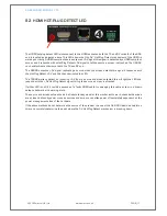
Page 16: ...with the TX or RX 866 units 8 2 HDMI DATA LED The HDMI data LED is located next to the HDBaseT RJ45 connector as indicated above This LED shows the flow of HDMI data and the type of HDMI data LED Sta...

Page 17: ...responds with the Hot Plug Detect 5V and this then illuminates the LED The TX866 waits to detect an incoming 5V from a source and when detected this will light the LED and respond with the 5V Hot Plu...

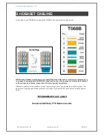
Page 18: ...inated there is a danger of damaging both the 4K 8x8 L output and receiver If you suspect an incorrectly terminated cable may have been applied please contact Smart e support immediately HDBaseT signa...

Page 19: ...5VDC 3A 2 1mm centre positive 11mm barrel with locking function Power Input Connector 2 1mmx5 5mm centre positive DC connector with locking function Operating temperature range 0 40 degrees Celsius S...

Page 20: ...None Output Ports 1x RJ45 female Gain 0 dB Pixel Bandwidth 340MHz Full Digital Interface Bandwidth 3 40Gbps Full digital a total of 10 2Gbps each colour is 3 40Gbps Maximum Resolution PC 1600x1200 60...

Page 21: ...with locking function Power Input Connector 2 1mmx5 5mm centre positive DC connector with locking function Operating temperature range 0 40 degrees Celsius Storage temperature range 20 60 degrees Cels...

Page 22: ...ne Gain 0 dB Pixel Bandwidth 340MHz Full Digital Interface Bandwidth 3 40Gbps Full digital a total of 10 2Gbps each colour is 3 40Gbps Maximum Resolution PC 1600x1200 60Hz 48 bit HDPC 1920x1200p 60Hz...

Reviews: