SMA Solar Technology AG
66
SB50US-80US-IUS094030
Installation Guide
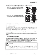
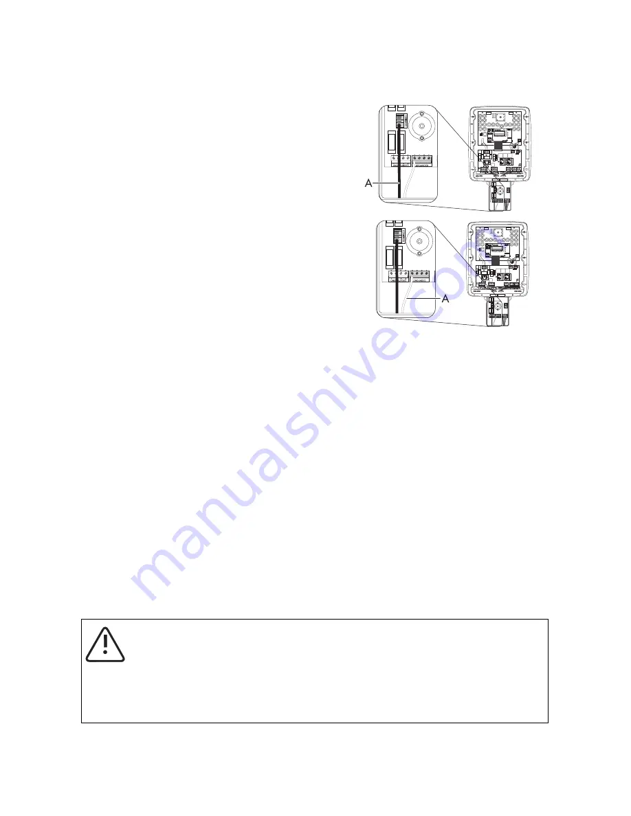
DC Connection With Additional DC-Distribution, Positive Grounding
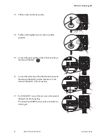
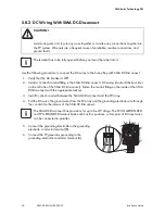
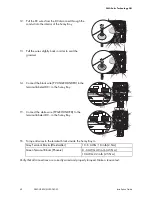
3. Torque all wires in the terminal blocks inside the SMA DC-Disconnect to 15 in-lb (1.7 Nm).
5.9 Communication
The Sunny Boy can be retrofitted with a communication interface (socket see section 3.2 "Locating
Internal Components" (page 19)) to communicate with special data acquisition devices (e.g. Sunny
WebBox) or a PC with appropriate software (e.g. Sunny Data).
For a complete listing of all applicable communication options please refer to the SMA web page or
the product catalogue.
See the communication interface documentation for a detailed wiring diagram and instructions for
insertion.
5.10 Closing the Sunny Boy
When you have finished connecting the AC-output wires, the DC-input wires, and the communication
cables, re-check all your connections to ensure that everything is in the right place and that all
connections and knockout fittings are secure and properly torqued. Check all of the knockout fittings
on the bottom of the Sunny Boy to ensure that they provide a weather-tight seal.
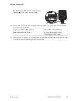
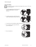
1. Connect the negative DC wire (A) to the terminal
labeled COMBINED in the SMA DC-Disconnect.
2. Connect the positive DC wire (A) to the terminal
labeled PV GROUNDED in the SMA DC-Disconnect.
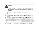
WARNING!
Never install the Sunny Boy during rain or very damp conditions. Because the Sunny Boy
is completely sealed, you must be sure no moisture is trapped inside the enclosure when
securing the lid.

