SMA Solar Technology AG
40
SB50US-80US-IUS094030
Installation Guide
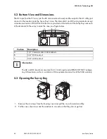
5.2 Bottom View and Dimensions
The DC input from the PV array (via the DC disconnect enclosure) and the output to the AC utility grid
connect to the inverter inside the Sunny Boy’s case. The internal AC and DC wiring terminals accept
a maximum wire size of #6 AWG. Knockouts are provided on the bottom of the Sunny Boy near each
of the terminals for the wires to enter the case, see Figure below.
5.3 Opening the Sunny Boy
1. Remove the six screws from the housing cover and pull the cover forward smoothly.
2. Put the cover, the screws and the washers to one side so that they do not get lost.
Position
Description
A
1/2“ Communication Cable Glands
B
3/4“ DC Knockout
C
3/4“ AC Knockout
Information
The AC and DC knockouts are sized for 3/4 inch rigid conduit (EMT). DO NOT enlarge
any of these holes, as this is a violation of UL requirements and will void the SMA warranty.

