6 Electrical Connection
SMA Solar Technology AG
Operating manual
65
SI44M-80H-13-BE-en-15
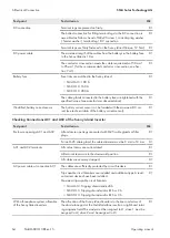
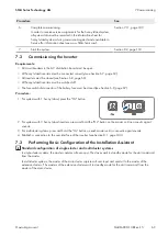
Checking the Generator Connection
Test point
Test criterion
Ok
The connection cables
The conductor cross-section is sufficient for the maximum generator
current.
☐
The cables are sufficiently protected by circuit breakers.
☐
With a three-phase off-grid system, al-
location of the line conductors
The allocation of the Sunny Island inverters to the line conductors of
the generator results in a right-hand rotating magnetic field. The master
must be assigned to L1, slave 1 must be assigned to L2, slave 2 must
be assigned to L3.
☐
Grounding
The exposed conductive part of the generator is grounded.
☐
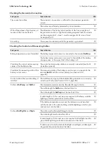
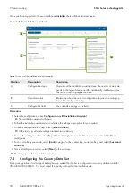
Checking the Control and Measuring Cables
Test point
Test criterion
Ok
Battery temperature sensor if installed
The battery temperature sensor is connected to the terminal
BatTmp
.
☐
The battery temperature sensor is secured in the middle of the battery-
storage system, in the upper third of the battery cell.
☐
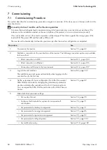
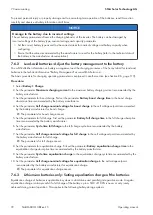
If installed, the control and measuring
cables of the Multicluster-Box
The control and measuring cables are correctly connected (see Multi-
cluster-Box manual).
☐
If installed, the measuring cable of the
battery current sensor
The measuring cable of the battery current sensor is connected to the
terminal
BatCur
with the correct polarity (see Section 6.5.9,
☐
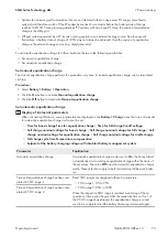
Control cable of the load shedding, if
installed
The multifunction relay and the load-shedding contactors are correctly
wired to each other (see Section 6.5.12, page 48).
☐
Cables at
BatTemp
and
BatCur
The insulated conductors must be threaded through a ferrite.
☐
The cable length for
BatCur
must be less than 3 m.
☐
The cable length for
BatTmp
must be less than 30 m.
☐
If cable lengths of 30 m and more are required for BatTemp, suitable
lightning protection precautions must be taken.
☐
If the battery temperature sensor and the batteries are not installed
with the inverter in the same building, suitable lightning protection pre-
cautions must also be taken.
☐
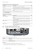
Cable at
BatVtgOut
and
DigIn
The cable must be threaded through a ferrite.
☐
The cable length must be less than 30 m.
☐
If cable lengths of 30 m and more are required for BatVtgOut and Di-
gIn, suitable lightning protection precautions must be taken.
☐
If cables are to be laid outside for BatVtgOut and DigIn, suitable light-
ning protection precautions must be taken.
☐

