background image

20 

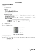
9.9  Battery current limitation 

 
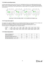
The battery current limitation is user adjustable according to the battery capacity, in order to ensure a battery reloading 
between 0.1C and 0.3C as advised by the manufacturer. The thresholds are 25%, 50% and 75% of the nominal current. 
Selection is made by 2 microswitches. The charging current default value is set at 75% of the nominal current. 


Figure 3: configurating battery current limitation using microswitches 1 & 2 


9.10  Temperature compensation (according VdS2122) 

 
Thanks to a battery voltage compensation system, the battery charge characteristics can be maintained within the 
specifications limits provided by the battery manufacturer under the whole range of temperature. 
The temperature is measured by a sensor placed as close as possible to the battery. 
Voltage values versus temperature values are:  


Temperature (°C) 

-20 

-10 

10 

20 

25 

30 

40 

50 

60 

12V 

14.13 

14.13 

14.13 

13.87 

13.69 

13.60 

13.49 

13.33 

13.20 

13.08 

24V 

28.27 

28.27 

28.27 

27.74 

27.38 

27.20 

26.98 

26.66 

26.40 

26.17 


9.11  Battery capacity 


Charger voltage (V) 

24 

24 

12 

12 

Charger current (A) 

Maximum battery charging current (A) 

1,5 

2,25 

4,5 

Specified capacity (Ah) - C20 - 1.75V 

26 

40 

50 

86 

Minimum capacity (Ah) - C20 –1.75V 


Summary of Contents for AXS3

Page 1: ...Code 180120008Ga NDU NOT120008Ha Edition 0320 NOTICE D UTILISATION P 1 OPERATING INSTRUCTIONS P 15 BEDIENUNGSANLEITUNG S 29 NOTICE D UTILISATION AXS3 grade 3 3rd grade EN 50131 6 50W 75W...

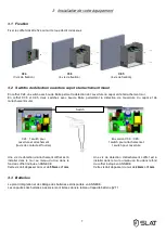
Page 2: ...on Basse 5 2 9 Limitation courant batterie 6 2 10 Compensation temp rature selon VdS2122 6 2 11 Capacit s batteries 6 3 Installation de votre quipement 7 3 1 Fixation 7 3 2 Switchs de d tection ouvert...

Page 3: ...ssion Ils sont conformes aux normes EN 60950 1 2006 A11 2009 A1 2010 A12 2011 A2 2013 Classe TBTS EN 62368 1 2014 EN 61000 6 1 2007 EN 61000 6 2 2005 EN 61000 6 3 2007 EN 61000 6 4 2007 A1 2011 EN 501...

Page 4: ...ntr e et de sortie 2 3 1 Entr e r seau tension monophas e 110V 240V fr quence 50 60Hz classe I r gimes de neutre TT TN IT disjoncteur bipolaire courbe C de calibre situ entre 2A et 10A pr voir en amon...

Page 5: ...2 d tections sont signal es par un m me contact sec 2 7 Protections Contre les inversions polarit s batterie avant et apr s mise sous tension Contre les surtensions au secondaire par transil d r gulat...

Page 6: ...a tension batterie permet de maintenir les caract ristiques de charge dans les limites de sp cifications du constructeur batteries sur toute la plage de temp rature d utilisation Une sonde plac e au p...

Page 7: ...s le mur au niveau du trou dans le fond du coffret indiqu en ANNEXE Cette vis doit d passer du mur de 55mm 1mm Une vis de d tection d arrachement coffret est installer dans le mur au niveau du trou da...

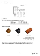
Page 8: ...5A Sortie utilisation 1x2pts 0 5 2 5 mm 15A Sortie batterie 1x2pts 0 5 2 5 mm 15A Reports 1x9pts 0 5 1 5 mm 14 5A D tail des fiches mobiles Secteur Sorties Communication Attention les ouvertures pr vu...

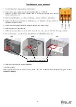
Page 9: ...es secteur utilisations et batteries fermer le disjoncteur secteur en amont 5 V rifier la tension de sortie utilisation La LED de la carte m re devient rouge 6 Raccorder les bornes de la batterie 7 V...

Page 10: ...s l utilisateur peuvent tre scell es par un plombage en coffret C38 et C85 et par autocollant sp cifique fournie en coffret C24 L autocollant sp cifique est placer sur l une des 2 vis en coffret C24 L...

Page 11: ...usqu 20 minutes apr s la disparition du d faut si tension batterie 1 75V lt 3 si imp dance interne trop lev e test toutes les 4h maximum sur une batterie charg e Les valeurs limites de l imp dance son...

Page 12: ...ERTISSEMENT Le remplacement de la batterie par une batterie de type incorrect peut engendrer un risque d explosion Les batteries usag es doivent tre mises au rebut conform ment aux obligations de recy...

Page 13: ...batterie ne prend pas le relais apr s un d faut secteur Contr ler la tension aux bornes de la batterie Contr ler le fusible batterie Contr ler la tension sur les bornes util 1 et ou util 2 Si les voy...

Page 14: ...14...

Page 15: ...15 NOTICE D UTILISATION P 1 OPERATING INSTRUCTIONS P 15 BEDIENUNGSANLEITUNG S 29 OPERATING INSTRUCTIONS AXS3 grade 3 3rd grade EN 50131 6 50W 75W...

Page 16: ...9 Battery current limitation 20 9 10 Temperature compensation according VdS2122 20 9 11 Battery capacity 20 10 Installation of your equipment 21 10 1 Mounting 21 10 2 Wall remover detection switches...

Page 17: ...and emission They are compliant with standards EN 60950 1 2006 A11 2009 A1 2010 A12 2011 A2 2013 TBTS class EN 62368 1 2014 EN 61000 6 1 2007 EN 61000 6 2 2005 EN 61000 6 3 2007 EN 61000 6 4 2007 A1...

Page 18: ...3 1 Mains input Single AC voltage 110V 240V Frequency 50 60Hz Class I Groundings TT TN IT Double pole breaker C curve rated current between 2A and 10A to provide upstream 12V 50W 75W Primary current 9...

Page 19: ...th detections are reported via a dry contact 9 7 Protections Against battery polarity inversion before and after switch on Against secondary overvoltages thanks to transil diode regulation troubles or...

Page 20: ...battery voltage compensation system the battery charge characteristics can be maintained within the specifications limits provided by the battery manufacturer under the whole range of temperature The...

Page 21: ...on the wall have to be install in the housing hole indicate in ANNEX to detect a tear down This screw must extend out of the wall by 24mm 1mm 10 3 Battery Batteries integration drawing and wiring sche...

Page 22: ...pts 0 5 2 5 mm 15A User output 1x2pts 0 5 2 5 mm 15A Battery output 1x2pts 0 5 2 5 mm 15A Alarm reports 1x9pts 0 5 1 5 mm 14 5A Moving plugs Mains Output Communication Important the openings provided...

Page 23: ...ery 4 After the electrical connections are made mains loads and batteries close the mains circuit breaker 5 Check the load output voltage The motherboard LED turns red 6 Connect the battery 7 Check th...

Page 24: ...stricted must be sealed by lead sealing in C38 and C85 housing and by a seal sticker in C24 housing The security seal sticker has to be stick on one of the 2 screw hole in C24 The lead sealing has to...

Page 25: ...ase a fault is detected another test will be performed every 30s until 20min have passed from fault end If battery voltage 1 75V elt 3 If internal impedance is too high a tests will be performed every...

Page 26: ...iated with improper use or incorrect maintenance of the equipment WARNING Replacing the battery with a battery of incorrect type may result in an explosion hazard Used batteries must be disposed of in...

Page 27: ...oad If the battery does not take over after a mains fault Check the voltage on the battery terminals Check the battery fuse Check the voltage on terminals load1 and or load2 If the indicator lights ar...

Page 28: ...28...

Page 29: ...29 NOTICE D UTILISATION P 1 OPERATING INSTRUCTIONS P 15 BEDIENUNGSANLEITUNG S 29 BEDIENUNGSANLEITUNG AXS3 grade 3 3rd grade EN 50131 6 50W 75W...

Page 30: ...begrenzung 34 17 9 Temperaturausgleich 34 17 10 Batteriekapazit ten 34 18 Installation Ihres Ger ts 35 18 1 Montage 35 18 2 Erkennungsschalter ffnen der Abdeckung und Abrei en von der Wand 35 18 3 Bat...

Page 31: ...011 A2 2013 Klasse TBTS EN 62368 1 2014 EN 61000 6 1 2007 EN 61000 6 2 2005 EN 61000 6 3 2007 EN 61000 6 4 2007 A1 2011 EN 50130 4 2011 EN 55022 2006 A1 2007 Klasse B UL1950 bei den Komponenten Sie si...

Page 32: ...n f r Ein und Ausg nge 20 3 1 Eingang Netz Einphasige Spannung 110V 240V Frequenz 50 60Hz Klasse I Sternschaltungen TT TN IT Vorgeschalteten bipolaren 2A bis 10A Nennwert Trennschalter zu vorsehen 12V...

Page 33: ...ber ein und den gleichen trockenen Kontakt bermittelt 17 7 Schutz Vor Polarit tsinversion der Batterie vor und nach dem Spannung zuschalten Vor sekund rseitiger berspannung entstehen durch Suppressord...

Page 34: ...Batteriespannung erm glicht die Beibehaltung der Ladungseigenschaften im Rahmen der Spezifikationen des Batterieherstellers ber die gesamte Spannbreite der Nutzungstemperatur Durch eine nahe an den B...

Page 35: ...Geh usebohrung gegen ber an der Wand zu befestigen Diese Schraube mu ber die Wand 55mm 1mm hinausragen Eine abrei en Erkennungsschraube ist dem im Anhang gezeichneten Geh usebohrung gegen ber an der...

Page 36: ...Ausgang Verbraucher 1x2pts 0 5 2 5 mm 15A Ausgang Batterie 1x2pts 0 5 2 5 mm 15A Berichte 1x2pts 0 5 1 5 mm 14 5A Einzelheiten zu den mobilen Steckverbindern Stromnetz Ausg nge Verbindung Achtung es...

Page 37: ...mnetz Verbraucher und Batterie den vorgeschalteten Netzschalter schlie en 3 Ausgangsspannung auf Verwendungsseite pr fen Die LED Anzeige der Grundplatine wird rot 4 Batterieklemmen anschlie en 5 Betri...

Page 38: ...Abdeckung des Modells C24 mit einem Sticker siehe Abbildung links versiegelt Die Sticker sind im Lieferumfang enthalten Der Sticker muss ber einen der beiden Verschraubungen des Modells C24 platziert...

Page 39: ...is zu 20 Minuten nach Behebung des Fehlers durchgef hrt falls Batteriespannung 1 75V Zelle 3 falls innere Impedanz zu hoch Test mindestens alle 4h an geladener Batterie Die Grenzwerte der Impedanz lau...

Page 40: ...einen falschen Batterietyp kann zu Explosionsgefahr f hren Verbrauchte Batterien m ssen gem den Materialr ckf hrungsverpflichtungen entsorgt werden 22 Schutz und Sicherungen 22 1 12V Versionen Bezeich...

Page 41: ...einer Netzst rung die Versorgung nicht bernimmt Spannung an den Batterieklemmen pr fen Batteriesicherung pr fen Spannung an den Klemmen Verbr1 und oder Verbr2 pr fen Falls die Kontrollleuchten nicht a...

Page 42: ...EXE APPENDIX ANHANG IMPLANTATION BATTERIES AUTORISEES AUTORISED BATTERY IMPLANTATION GENEHMIGTE BATTERIENANORDNUNG COFFRET CABINET GEH USE C24 COFFRET CABINET Geh use C38 12V 7Ah 12Ah 12V 17Ah 24V 7Ah...

Page 43: ...43 COFFRET CABINET GEH USE C85 12V 86Ah 12V 65Ah 24V 38Ah 24V 24Ah 26Ah...

Page 44: ...N DE MONTAGE MOUNTING DRAWING MONTAGEZEICHNUNG COFFRET CABINET GEH USE C24 Trou pour vis de d tection d arrachement mural Hole of the screw use to detect housing tear down Bohrung f r die abrei en Erk...

Page 45: ...45 COFFRET CABINET GEH USE C38 Trou pour vis de d tection d arrachement mural Hole of the screw use to detect housing tear down Bohrung f r die abrei en Erkennung...

Page 46: ...46 COFFRET CABINET GEH USE C85 Trou pour vis de d tection d arrachement mural Hole of the screw use to detect housing tear down Bohrung f r die abrei en Erkennung...

Page 47: ...47...

Page 48: ...BP66 69543 CHAMPAGNE AU MONT D OR Cedex France Tel 33 0 4 78 66 63 60 E mail comm slat fr SLAT GmbH Leitzstra e 45 70469 Stuttgart Deutschland Tel 49 0 711 899 890 08 Fax 49 0 711 899 890 90 E mail in...

Reviews: