CANopen Agile
06/2010
14
Connection
4.2
Disassembly
•
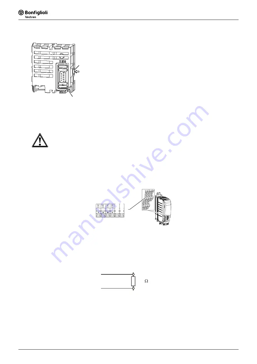
Remove the cover of the module slot.
2
1
•
Loosen the screw (1) on the communication module.
•
Using a small screwdriver, firstly unlock the right and then the
left snap-in hook (2).
•
Remove the communication module from the slot.
•
Unscrew the PE spring.
•
Replace the cover onto the frequency inverter.
5 Connection
The CAN-Connection of the Systembus is physically laid out according to ISO-DIS 11898 (CAN High
Speed).
Caution!
The frequency inverter must be disconnected from the power supply before installation and
connection work. Make sure that the frequency inverter is de-energized.
Installation under voltage is not permitted and can lead to the destruction of the frequency
inverter and/or the communication module.
5.1
Connection to the Terminals
Connect the bus to the X12.5 and X12.6 terminals of the frequency inverter.
X12
5 6
CA
N
Hi
gh
CA
N
Lo
w
Cable
•
For the bus line use a twisted and shielded cable.
•
Implement the shield as a braided shield (not a foil shield).
•
Connect the cable shield surfaces to PE at both ends.
Bus Termination
Connect the bus termination, necessary on one cable, at the first and last physical participant.
CAN High
120
CAN Low
Data line
Data line
Summary of Contents for Bonfiglioli Vectron Agile
Page 1: ...Agile CANopen Communication manual Frequency inverter 230V 400V ...
Page 2: ......
Page 103: ......


