background image

27

SKOPE TME650/1000

Replacement Procedures

Service Manual

Interior Light

The chiller interior is lit by either one or two light tubes which can be replaced 
without moving shelves or removing product.The procedure for changing the 
interior lights is the same for fluorescent and LED tubes. 

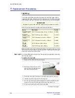
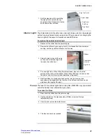
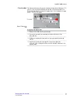
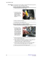
To replace the cabinet interior light

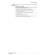
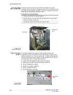
Fuses

The fuse for the cabinet lights and centre pillar (TME1000 only) are located 
under the ballast cover (below the sign panel).

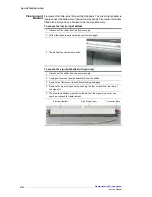
To access the fuses

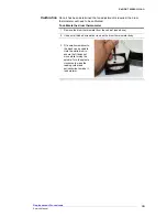
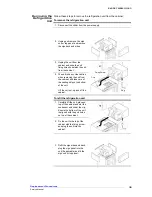
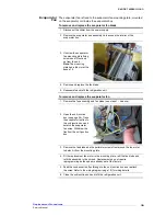
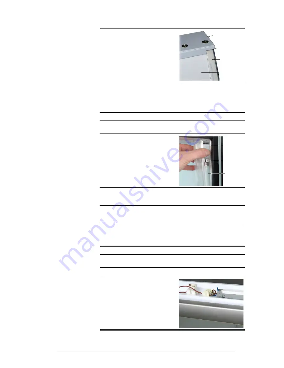
7. Refit the sign panel. When refitting 

the sign panel, ensure both sign 
panel end strips fit neatly into the top 
and bottom corner notches.

Sign Top Cover

Corner Notch

Sign Panel 
End Strip

Sign Panel

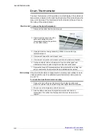
1. Disconnect the chiller from the power supply. 

2. Remove the diffuser by squeezing it until it is released from the aluminium 

housing, and then push the diffuser out of the way.

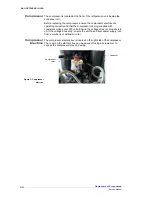
3. Rotate the light tube until the pins 

on the ends of the tube align with 
the slots, then slide it out.

4. Fit a new light tube. When fitting fluorescent tubes, take care that the 

printing on the tube is at the bottom. When fitting LED tubes, take care that 
the ‘power’ end is at the top (tube orientation is important).

5. Refit the diffuser by slipping the back section into the housing, then 

squeezing and snapping the front section of the diffuser into place as you 
work down the length of the light.

Light tube

Diffuser

Pins aligned 
with slot

1. Disconnect the chiller from the power supply. 

2. Unplug and remove the sign assembly (if fitted) or remove the sign 

replacement panel.  

3. Unscrew and remove the ballast cover.

4. The fuse can now be accessed.

Summary of Contents for TME1000

Page 1: ...TME650 1000 Service Manual MAN7462 Rev 1 2 Nov 2016 SKOPE Glass Door Vertical Chiller...

Page 2: ...oduct is infringed if the owner for the time being does any of the following Applies the trade mark to the product after their state condition get up or packaging has been altered in any manner Alters...

Page 3: ...650 18 Door Assembly TME1000 19 Sign Assembly TME650 20 Sign Assembly TME1000 21 Side Light Assembly 22 Electrics Box Assembly 23 Unit Assembly TME650 24 Unit Assembly TME1000 25 4 Replacement Procedu...

Page 4: ...Unit Junction Box Assembly 36 High Pressure Switch 36 Thermostat 37 Condenser Fan 38 Evaporator Fan 39 Compressor 40 Compressor Electrics 40 5 Maintenance Cleaning 41 Cabinet 41 Condenser Coil 41 6 T...

Page 5: ...tion 50mm thick polyurethane foam Cyclo iso Pentane blowing agent C5H10 C5H12 Doors 1 x Self closing aluminum framed double glazed toughened safety glass swing door Dimensions External Internal Height...

Page 6: ...740mm 640mm Depth 700mm 570mm Floor area 0 52m2 Internal volume 610 litres Shelves 5 x wire shelves 620mm wide x 480mm deep Operating conditions Max operating temp 40 C Cabinet temp range 1 C to 4 C E...

Page 7: ...m 1030mm Depth 700mm 570mm Floor area 0 79m2 Internal volume 980 litres Shelves 5 x wire shelves 1010mm wide x 480mm deep Operating conditions Max operating temp 40 C Cabinet temp range 1 C to 4 C Ele...

Page 8: ...oughened safety glass swing door Dimensions External Internal Height 2195mm 1560mm Width 1130mm 1030mm Depth 700mm 570mm Floor area 0 79m2 Internal volume 980 litres Shelves 5 x wire shelves 1010mm wi...

Page 9: ...9 SKOPE TME650 1000 Specifications Service Manual Notes...

Page 10: ...w grn ylw grn ylw grn ylw grn ylw grn ylw grn ylw grn ylw orange orange Sensors P S C H L T S E N P M M P E N P E N LEGEND 1 Sign unit 8 Start capacitor 15 Evaporator fan motor 2 Fluorescent tube 9 Re...

Page 11: ...lw grn ylw grn ylw grn ylw grn ylw grn ylw grn ylw grn ylw grn ylw orange Sensors P S C H L T S E N P M M P E N P E N white LEGEND 1 Sign unit 8 Relay 15 Socket box 2 LED tube 9 Unit junction box 16 3...

Page 12: ...grn ylw grn ylw grn ylw grn ylw grn ylw grn ylw orange orange orange C H L P S T S E N P M P E N M P E N Sensors LEGEND 1 Sign unit 9 Relay 17 3 Pole ENSTO socket 2 Fluorescent tube 10 Unit junction b...

Page 13: ...lw grn ylw grn ylw grn ylw grn ylw grn ylw grn ylw grn ylw grn ylw C H L P S T S E N P M P E N M P E N Sensors blue brown white white LEGEND 1 Sign unit 9 Unit junction box 17 Control panel 2 LED tube...

Page 14: ...14 Spare Parts Service Manual SKOPE TME650 1000 3 Spare Parts Cabinet Assembly TME650 1 2 3 3 4 5 6 7 8 9 10 11 12 13 14 15 16 17 20 C...

Page 15: ...0973 99 8 Sidelight asembly fluorescent lit V6070 L85RD 32 Sidelight assembly LED lit V50BV L85R 32 Sidelight cover V5060 E71 9 Single fluorescent ballast Vossloh Schwabe fluorescent lit cabinet only...

Page 16: ...16 Spare Parts Service Manual SKOPE TME650 1000 Cabinet Assembly TME1000 5 C 1 2 3 3 4 5 6 7 8 10 11 12 13 15 16 17 18 20 14 9 19...

Page 17: ...ED lit V50BV L85R 32 Sidelight cover V5060 E71 9 LH Sidelight asembly fluorescent lit V5070 L85LD 32 LH Sidelight assembly LED lit V50BV L85L 32 Sidelight cover V5060 E71 10 Twin fluorescent ballast V...

Page 18: ...TME650 Parts TME650 Door Item Description SKOPE Part No Customer Part No 0 RH door assembly V6000 Z01RT LH door assembly V6000 Z01LT 1 Door gasket GKT4775N 2 Torsion bar assembly REF4295P 3 Capstan TU...

Page 19: ...ME1000 Parts TME1000 Door Item Description SKOPE Part No Customer Part No 0 RH door assembly V5000 Z01RT LH door assembly V5000 Z01LT 1 Door gasket GKT4774N 2 Torsion bar assembly REF4295P 3 Capstan T...

Page 20: ...sign assembly V60BA T23 32 00 1 Front panel clear PLY9064 2 Sign end RH V50BA T25 32 3 Sign end LH V50BA T26 32 4 Fluorescent tube ELL0601 5 Lamp holder ELZ0600 Item Description SKOPE Part No Custome...

Page 21: ...nt sign assembly V50BA T23 32 00 1 Front panel clear PLY9097 2 Sign end RH V50BA T25 32 3 Sign end LH V50BA T26 32 4 Fluorescent tube ELL0602 5 Lamp holder ELZ0600 Item Description SKOPE Part No Custo...

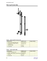
Page 22: ...t No 0 Fluorescent RH sidelight assembly V6070 L85RD 32 0 Fluorescent LH sidelight assembly TME1000 only V5070 L85LD 32 1 Fluorescent tube ELL0604 2 Lamp holder ELZ0600 Item Description SKOPE Part No...

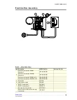
Page 23: ...Electrics box assembly TME1000 fluorescent V5070 E50EPSZ Electrics box assembly TME650 LED V5084 E50EPSZ Electrics box assembly TME1000 LED V6080 E50EPSZ 1 Thermostat ELO7702 2 High pressure switch EL...

Page 24: ...4A Condenser fan blade FAN4100 Condenser fan shroud V5522 232 Condenser motor mount UT40AA 235 6 Unit base V6070 210 32 7 Evaporator foamed box V6071 376 8 Evaporator foamed lid V5500 377 9 Suction li...

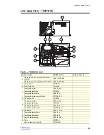
Page 25: ...enser fan blade FAN4100 Condenser fan shroud V5020 232 Condenser motor mount UT40AA 235 6 Unit base V5071 210 32 7 Evaporator foamed box V5071 376 8 Evaporator foamed lid V8150 225 9 Suction line asse...

Page 26: ...uorescent or LED Version Description Part No Fluorescent interior TME650 1000 35W T5 fluorescent tube 16mm x 1450mm ELL0604 LED interior TME650 1000 22W T8 LED tube 26 x 1500mm ELL10180 Fluorescent si...

Page 27: ...ller from the power supply 2 Remove the diffuser by squeezing it until it is released from the aluminium housing and then push the diffuser out of the way 3 Rotate the light tube until the pins on the...

Page 28: ...allast lit sign only 1 Disconnect the chiller from the power supply 2 Follow the steps to access the fuses previous page 3 The ballast can now be accessed 1 Disconnect the chiller from the power suppl...

Page 29: ...o realign Door Tension The glass door has an internal torsion bar pretensioned at the factory which enables the door to self close If necessary door tension can be further adjusted by rotating the cap...

Page 30: ...the aluminium tube moves freely up and down the torsion bar 6 Fit the new torsion bar assembly into the door frame When the torsion bar is correctly installed the capstan should not turn 7 Lightly ta...

Page 31: ...ging 1 Disconnect the chiller from the power supply 2 Remove the door see Door Removal on previous page 3 Remove the torsion bar assembly from the door see Torsion Bar Replacement on page 30 4 Refit t...

Page 32: ...ermometer bulb from the port hole on the cabinet ceiling 3 Unplug and remove the sign assembly if fitted or remove the sign replacement panel 4 Unscrew and remove the control panel cover 5 Unscrew and...

Page 33: ...calibrate the drum thermometer 1 Remove the drum thermometer from the cabinet see above 2 Use a small bladed screwdriver to open the drum thermometer body 3 Fit a small screwdriver to the black centre...

Page 34: ...odel number is printed on the unit rating serial number label attached to the side of the evaporator box Top mount SKOPE Cyclone refrigeration unit Chiller Model TME650 fluorescent TME650 LED TME1000...

Page 35: ...detatch the unit from the cabinet 4 The unit is heavy Use caution when removing the unit from the cabinet and take care of the sealing strip on the bottom of the unit Lift the unit out up and off the...

Page 36: ...ed on top of the unit junction box If it becomes necessary to reset the high pressure switch determine and eliminate what caused the high pressure switch to activate before resetting Conditions that m...

Page 37: ...to make warmer turn anti clockwise To replace the thermostat Figure 5 Thermostat dial Thermostat 1 Disconnect the chiller from the power supply 2 Remove the evaporator box assembly lid to access the...

Page 38: ...blade see steps 1 3 above 2 Open the unit junction box see page 36 Trace the condenser fan flex to the unit junction box and detatch the condenser fan wires black and blue from the fan capacitor brown...

Page 39: ...de 5 Reassemble and refit the refrigeration unit 1 Remove the fan assembly and fan blade see steps 1 4 above 2 Open the unit junction box see page 36 Trace the evaporator fan flex to the unit junction...

Page 40: ...is being supplied with consistent voltage over 220 volts Ensure the voltage does not drop at start up If the voltage does drop ensure the unit has a direct power supply not from a multi box or extens...

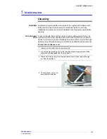
Page 41: ...erms the condenser coil must be cleaned each month with a soft brush or vacuum cleaner to remove any dust or blockage from the coil fins A more thorough cleaning is recommended every six months by qua...

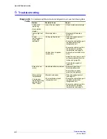
Page 42: ...n unit Ensure the cabinet is within the maximum operating temperature see page 5 Cabinet door is opened excessively Ensure door is closed more often Adjust the door tension and if necessary replace th...

Page 43: ...hurch New Zealand Freephone 0800 947 5673 Fax 03 983 3896 E mail enquiry skope co nz Website www skope co nz AUSTRALIAN CONTACT A B N 73 374 418 306 PO Box 7543 Baulkham Hills B C NSW 2153 Australia F...

Reviews: