


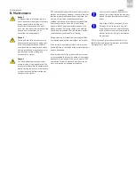


6. Operation
page 41
EN
6.5 Setting the air flow rate
The amount of air required is based on the quanti-
ties of lubricant that will be fed, the number of
lubrication point lines and the specific characteris-
tics of the lubrication point. The operating pressure
of the compressed air must be set at a level that
provides an air volume sufficient to reliably trans-
port the oil streak, taking into account pressure
losses in the lubrication point line and the lubrica-
tion point.
The setting for air flow rate is determined empiri-
cally. The most important criterion is visual ob-
servation of a continuous, uniform lubricant flow in
the lubrication point lines. A lubrication point line
with an internal diameter of 2.3 mm requires
approximately 1,000 to 1,500 Nl/h of compressed
air to transport an oil streak properly.
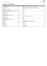
This value applies to all oils of viscosity classes ISO
VG 32 to ISO VG 100. Higher values apply to
higher-viscosity oils and oils with bonding additives.
The air pressure must be set at a level sufficient to
deliver this compressed air volume in each
lubrication point line, taking into account pressure
losses in the lubrication point line and the bearing
assembly. The available air pressure at the com-
pressed air inlet (connection to compressed air
supply) should be at least 3 bar, but preferably a
minimum of 6 bar.
When using high-speed rolling bearings, higher air
pressure is required in order to overcome bearing
back pressure (air turbulence). To ensure reliable
operation of the oil + air lubrication system, the air
pressure at the nozzle (inlet to the bearing) should
not be below 1.5 bar
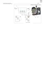
The operating pressure of the oil + air lubrication
system is set using the pressure control valve for
compressed air (item 6 in Fig. 1). The air pressure
should be between 3 and 10 bar. The air flow rate
in the individual lubrication point lines is set using
the corresponding air adjustment screw (item 10 in
Fig. 2 and 3) on the oil + air metering unit (item 9 in
Fig. 1).
Note:
The lubrication point outlet on the oil + air metering
unit cannot be completely closed using the air
adjustment screw. A minimum air flow rate is
always maintained. Changing the air flow rate for
one lubrication point line always affects the air flow
rate in the other lubrication point lines.
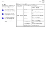
In the event of malfunctions in pressure build-up,
the oil + air lubrication system and the machine
must be switched off to prevent underlubrication of
the lubrication point.
Summary of Contents for OLA Series
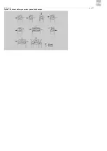
Page 19: ...3 Design and function page 19 EN Figure 4 Hydraulic diagram of oil air lubrication system ...
Page 49: ...blank page ...
Page 50: ...blank page ...
Page 51: ...blank page ...


