

3. Design and function
page 17
EN
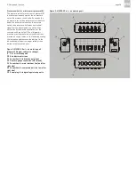
Oil + air metering unit (9)
Oil + air metering units are available in two differ-
ent model designs which differ in terms of available
metered quantities of lubricant (see Table 5, Chap.
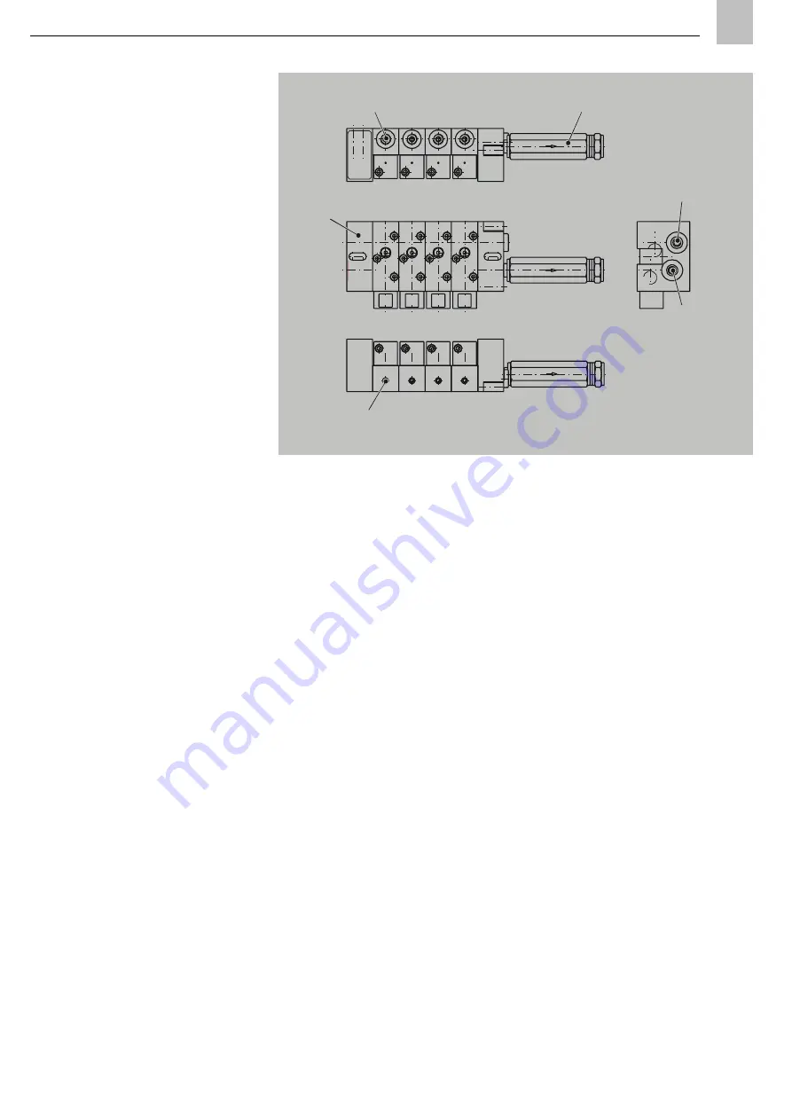
6.4). The MV20X-20 model design (Fig. 2) is de-
signed for metered quantities between 10 mm³
and 160 mm³ (six gradients). The MV50X model
design (Fig. 3) supports metered quantities of
2 mm³ and 6 mm³.
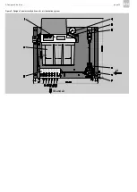
An oil + air metering unit (Fig. 2 and 3) consists of
a valve block in compact design with a maximum of
six (MV50X) or a maximum of eight (MV20X-20)
lubrication line connections. Multiple oil + air
metering units can be connected in series if more
lubrication line connections are required. In the oil
+ air metering unit, the lubricant is separately
metered for each lubrication point and transported
by the air stream into the lubrication point line and
through to the lubrication point. The air stream
required for each lubrication point can be set
individually using the air regulating screws in the
oil + air metering units.
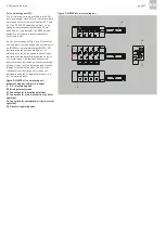
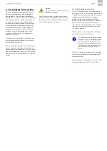
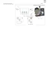
Figure 3: MV50X oil + air metering unit
Figure 3: MV50X oil + air metering unit
(schematic diagram, subject to change)
9 Oil + air metering unit
10 Air adjustment screws
11 Connection for lubrication point lines
13 Connection for main lubricant line (on left or
right side)
14 Connection for compressed air line (on left or
right side)
16 Pressure-regulating valve
06
02
06
06
A
B
A
B
OIL
AIR
9
10
11
13
14
16
Summary of Contents for OLA Series
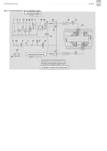
Page 19: ...3 Design and function page 19 EN Figure 4 Hydraulic diagram of oil air lubrication system ...
Page 49: ...blank page ...
Page 50: ...blank page ...
Page 51: ...blank page ...


