


9. Faults
page 45
EN
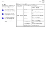
9. Faults
Table 6 gives an overview of possible malfunctions
and their causes. If you are unable to rectify the
malfunction, please contact SKF Lubrication
Systems Germany GmbH Service.
You must not dismantle the product or
parts of the product during the warranty
period. Doing so invalidates all warranty
claims.
All other work relating to installation,
maintenance, and repair must only be
carried out by SKF Lubrication Systems
Germany GmbH Service.
Only original SKF Lubrication Systems
Germany GmbH spare parts may be
used. It is prohibited for the operator to
make alterations to the product or to
use non-original spare parts and
resources.
Table 6: Fault analysis and rectification
Malfunction
Possible cause
Rectification
Motor fails to start when
the operating voltage is
applied
No operating voltage on motor
Check mains connection.
Check mains plug/cable and connect properly if
necessary.
Check operating voltage on motor.
Check fuse.
Check motor circuit breaker.
Pump blocked
Measure motor current. If current is impermissibly
high:
Dismantle pump, crank by hand:
If resistance is high, replace the pump.
Motor jammed
Measure motor current. If current is impermissibly
high:
Dismantle motor, crank by hand:
If resistance is high, replace the motor.
Motor runs with difficulty
and at a low speed
Sluggish pump
Measure motor current. If current is impermissibly
high:
Dismantle pump, crank by hand:
If resistance is high, replace the pump.
Sluggish motor
Measure motor current. If current is impermissibly
high:
Dismantle motor, crank by hand:
If resistance is high, replace the motor.
Impermissible lubricant (see
technical data)
Remove lubricant from entire system and dispose of
lubricant in the proper manner; fill system with suitable
lubricant.
Pressure too high, pressure-
regulating valve is jammed or
defective
Check pressure-regulating valve and replace if
necessary.
Ambient temperature too low
(see technical data)
Increase ambient temperature.
Summary of Contents for OLA Series
Page 19: ...3 Design and function page 19 EN Figure 4 Hydraulic diagram of oil air lubrication system ...
Page 49: ...blank page ...
Page 50: ...blank page ...
Page 51: ...blank page ...


