


4. Installation instructions
page 24
EN
The electronic control unit is connected using a
rectangular connector as per DIN EN 175301-
803-A (clamping range Ø 8 - 10 mm).
Danger!
The available mains voltage (supply
voltage) must be in accordance with the
specifications on the rating plate of the
motor or of the electrical components.
Check the fuse protection of the elec-
trical circuit. Use only fuses with the
prescribed amperage, as bodily injury
and property damage may otherwise
result.
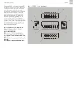
Details on the electrical connection of the motor to
the power supply, especially terminal and connec-
tor pin assignment, can be found in the documen-
tation for the oil + air lubrication system.
If no documentation is available, you can
request the documentation directly from
SKF Lubrication Systems Germany
GmbH.
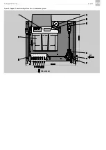
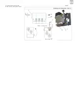
The electrical circuit diagram of the compact unit is
affixed inside the unit's cover cap and can be
accessed by removing the cap. This diagram is
affixed in such a way that it cannot be removed.
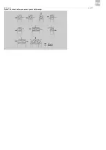
4.3.2 Inductive loads
In the case of switches with inductive loads, they
must be low-inductive in order to keep wear on
contact areas to a minimum. Otherwise, there is a
danger of damaging the contact surfaces of the
switch elements. Appropriate measures should be
used to protect the contacts of the switch ele-
ments.
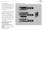
The connection of electrical switching devices such
as the fill level switch, pressure switch, control
valves, thermometer, etc. is to take place in accor-
dance with the specifications in the documentation
of the oil + air lubrication system.
If no documentation is available, you can
directly request the documentation from
SKF Lubrication Systems Germany
GmbH.
Summary of Contents for OLA Series
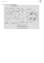
Page 19: ...3 Design and function page 19 EN Figure 4 Hydraulic diagram of oil air lubrication system ...
Page 49: ...blank page ...
Page 50: ...blank page ...
Page 51: ...blank page ...


