16 Adapting the Water Unit
Sirona Dental Systems GmbH
59 58 470 D 3370
22
D 3370.031.01.10.02
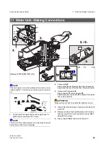
3.
Loosen (do not remove) the nuts on screws
F
of the fix-
ing bracket
B
.
4.
Screw and tighten brackets
B
on the floor with screws
and washers to floor:
– With a
concrete floor
:
Use 10 x 160 wood screws
– With a
wooden floor
:
Use 10 x 80 wood screws
– With the
M1 adapter plate
(refer also to page 42):
Use M10 x18
WARNING
Do not secure the water unit by means of the 2 drill
holes E.
5.
Use a spirit level to vertically align the water unit in all di-
rections and place shimming plate underneath the unit,
if necessary.
6.
Tighten screws
A
.
7.
Tighten the nuts of screws
F
.
8.
Pull hoses and cables into the junction box area of the
chair.
NOTE
i
Adapt the length of the suction and drain hoses to suit local
conditions. Cut off pieces of superfluous hose, if any.
9.
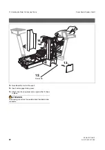
Grease O-rings and insert the end-piece of the
drain
hose
(
small
hose diameter
) and of the
suction hose
(
large
hose diameter)
.
ATTENTION
Make sure that the suction pipe is connected as the suction
pipe - in other words, not mistaken for the drain.
Make sure the drain slopes over its whole length. Do not
place other hoses on it.
The drain is not required if the water is removed centrally by
suction. If the drain pipe is present, you must cover it.
58
71
848
D3370
58
71
848
D3370
Grease SYNTHESO PRO AA2
B
A
A
F
5.
8.
8.
4.
10 x 160 (2 ea.)
10 x 80 (2 ea.)
2. / 3. / 6.
E
F
7.
M8x20 (2 ea.)


