28 Compare and adjust operating air pressures
Sirona Dental Systems GmbH
59 58 470 D 3370
38
D 3370.031.01.10.02
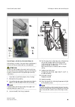
Setting the Air Pressures
Propellant air
The setting is performed separately for each turbine on the
chip
BS
concerned.
•
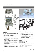
Take the instruments from their holders.
•
Press down two catches
A
and remove the instrument
tray.
•
Loosen screws
B
.
•
Lift back the unit cover
C
, and secure with the upright
retaining device
D
.
•
Set down the instrument tray temporarily and return the
instruments to their holders (photelectric light barrier
detection must function).
•
Remove the turbine and screw 4-on-1 probe
V
between
the turbine and hose.
•
Start the turbine with the foot switch.
•
Set the pressure of the propellant air at
RD5
with a
screwdriver.
Do not undo the screw further than to the level of
the plastic collar.
•
Repeat setting for other holders.
•
Close the unit head:
– Take out the instruments and remove the instru-
ment tray.
– Fold down the unit head and install screws
B
.
When installing the unit head, make sure that is
centered with respect to the chassis so that
gaps of identical size are created when the
instrument tray is mounted.
– Put the instrument tray in place and lay the instru-
ments on it.
Spray air
•
Connect the 4-on-1 probe.
•
Undo union nut
M
.
•
Using a screwdriver, set spray air pressure SL as re-
quired by the customer by turning screw
S
.
•
Tighten union nut
M
•
Check the settings and readjust if necessary.
•
Remove the 4-on-1 probe.
BS
RD5
-
+
A
B
C
D
V
S
M
TL
SL


